LED means light emitting diode,PCB means printed Circuit board
So, led pcb is printed circuits board for light emitting diode. Currently in order to provide LED lighting’s life, LED lighting factory always use
Metal core PCB for solder the LEDs Chip to the Circuit boards!
As Metal Core PCB means the base material for PCB is metal, but not normal FR4-
CEM1-3, etc, and currently what the metal used are Aluminum, Copper alloy.
MCPCBs are used instead of traditional FR4 or CEM3 PCBs because of the ability to
efficiently dissipate heat away from the components. This is achieved by using a
Thermally Conductive Dielectric Layer.
The main difference between a FR4 board and MCPCB is the thermally conductive
dielectric material in the MCPCB. This acts as a thermal bridge between the IC components
and metal backing plate. Heat is conducted from the package through the metal core to an
additional heat sink. On the FR4 board the heat remains stagnant if not transferred by a
topical heatsink. According to Avago’s white paper a MCPCB with a 1W LED
remained near an ambient of 25C, while the same 1W LED on a FR4 board reached 12C over ambient.
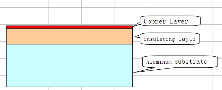
Aluminium PCB Construct:
- Circuit layer
- Insulatinglayer
- Aluminum substrate
Advantage of LED PCB
- heat dissipation
Some LEDs dissipate between 2-5W of heat and failures occur when the heat from a LED is not properly removed;
a LED’s light output is reduced as well as degradation when the heat remains
stagnant in the LED package. The purpose of a MCPCB is to efficiently remove the
heat from all topical IC’s (not just LEDs). The aluminum base and thermally conductive
dielectric layer act as bridges between the IC’s and heat sink. One single heat sink is
mounted directly to the aluminum base eliminating the need for multiple heat sinks
on top of the surface mounted components.
- thermal expansion
Thermal expansion and contraction is the common nature of the substance,
different CTE is different in thermal expansion. As its own characterics,
aluminum and copper have unique advance than normal FR4,
thermal conductivity can be 1.0~7.0 W/c.K
- dimensional stability
It is clear that the size of the metal-based printed circuit board more stable than insulating materials.
The size change of 2.5 ~ 3.0% when Aluminum PCB and aluminum sandwich
panels was heated from 30 ℃ to 140 ~ 150 ℃.
- ase material: Aluminum/Copper/Iron Alloy
- Thermal Conductivity (dielectrial layer): 0.8, 1.5, 2.0, 3.0 W/m.K.up to 10 w/m.k
- Board Thickness: 0.5mm~3.0mm(0.02″~0.12″)
- Copper thickness: 0.5 OZ, 1.0 OZ, 2.0 OZ, 3.0 OZ, up to 10 OZ
- Outline: Routing, punching, V-Cut
- Soldermask: White/Black/Blue/Green/Red Oil
- Legend/Silkscreen Color: Black/White
- Surface finishing: Immersion Gold, HASL, OSP
- Max Panel size: 600*1500mm(23.62″*59”)
- Packing: Vacuum/Plastic bag
- Samples L/T: 4~6 Days
- MP L/T: 5~7 Days
About Price:
Price is based on the requirement of LED PCB
- PCB thickness: 0.6 – 3.0mm, always thickness more ,price higher
- Thermal conductivity: 1.0 –10 W/m.k , thermal conductivity higher, price higher
- Material factory: Bergquist,Laird ETC, made in US factory that is more expensive than China