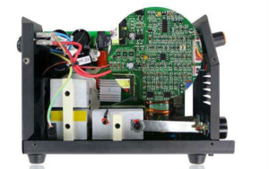
With the development of technology, technology requirements, more and more circuit boards are now used surface mount components, compared with the traditional package, it can reduce the area of the circuit board, easy to bulk processing, wiring density. Chip resistors and capacitors lead inductance greatly reduced, in the high-frequency circuit has great advantages. The inconvenience of surface mount components is not easy for manual soldering. To this end, circuit board welding engineers to common PQFP package chip, for example, describes the basic placement of surface mount components.
First, the required tools and materials
Welding tools need to have 25W copper small soldering iron, gold bridge electrode, the conditions can be used to adjust the temperature and ESD protection with the soldering station, pay attention to the soldering iron tip to the top, the width of the top can not be greater than 1mm. A pointed tweezers can be used to move and fix the chip as well as check the circuit. But also to prepare thin wire and flux, isopropyl alcohol and so on. The purpose of using flux is to increase the flowability of the solder so that the solder can be traction with a soldering iron and is smoothly wrapped around the pins and pads by means of surface tension. After soldering, remove the flux from the plate with alcohol.
Second, the welding method
1, circuit board welding engineers to remind the majority of readers in the welding before the application of flux on the pad, with a soldering iron again, so that the solder tin bad or oxidation, resulting in poor welding, the chip is generally no need to deal with.
2, with tweezers carefully PQFP chip on the PCB board, be careful not to damage the pin. Make it aligned with the pad, to ensure that the chip placed in the correct direction. The temperature of the soldering iron to more than 300 degrees Celsius, the tip of the tip with a small amount of solder, with the tool down to hold the position of the chip has been aligned in the two diagonal position of the pin with a small amount of flux, Hold down the chip, welding the two diagonal position of the pin, so that the chip fixed and can not move. After rewiring the diagonal, check the position of the chip for alignment. If necessary, adjust or remove and re-align the PCB.
3, start welding all the pins, should be added on the tip of the soldering iron, all the pins coated with flux to keep the pin moist. Touch the tip of each pin of the chip with a tip until you see solder flow into the pin. In the welding to keep the tip and the welding pin parallel to prevent the occurrence of overlap due to excessive solder.
4, after all the pins are soldered, wet all pins with solder to clean the solder. Absorb any excess solder in the place where you need to eliminate any shorts and lap. Finally, with tweezers to check whether there is Weld, check the completion of the removal of flux from the circuit board, the bristle brush soaked in alcohol along the direction of the pin carefully wipe until the flux disappeared.
5, the circuit board welding engineers to remind you that the chip resistance and capacitance components are relatively easy to weld some, you can first point in a solder on the tin, and then put the components of a head, with tweezers clamp components, welding a head, look To see if it is put; if it has been put, then another welding. To master the welding skills requires a lot of practice.

