The solution of impedance matching technology can not match the via holes size
Impedance matching technology solution
Global LTE smart phone shipments, network configuration and spectrum allocation is now growing rapidly, and 3GPP Telecommunications Standards Organization has been allocated for the LTE standard more than 40 bands. As the number of users and traffic load continues to increase, leading carriers such as AT & T and Verizon have begun to adopt LTE-Advanced Carrier Aggregation technology to increase the speed and capacity of the network. 3GPP has now identified more than 60 combinations of frequency bands, including in-band and inter-band aggregation.
For this reason, smart phones need to optimize the technology to meet the increasing spectrum allocation scheme and the possibility of carrier aggregation. For LTE radios in handsets, this means that the radio must be able to “tune” any of these bands, further requiring the antenna to maintain high efficiency across all frequency bands.
But it is easier said than done, the design efficiency of the antenna far more difficult to set requirements. In the early days of cell phone production, the antenna was the final consideration for signal RF system designers. Early mobile phone volume, low data rate, with only four bands worldwide. These factors ensure that the high signal performance of early mobile phone performance is not a problem. Fast forward to 2015, with the big screen and large batteries become mainstream, mobile phones have evolved into sophisticated smart phones. Original equipment manufacturers are increasingly using multiple antenna tuning techniques to ensure LTE signal performance across multiple bands.
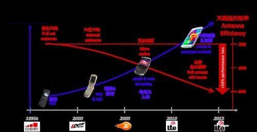
Mobile phone evolution and the corresponding antenna efficiency
LTE RF is the most critical RF front-end (RFFE), including antenna and analog data processing. RFFE’s power amplifiers, filters and power converters are designed to operate at a maximum efficiency of 50 ohms – the target impedance of the antenna feed-side (antenna and RFFE connections).
The antenna impedance at the antenna feed end depends on the type of antenna. The most widely used mobile device is the dual-band PIFA antenna. In the resonant frequency, the impedance of the antenna feed point is pure resistance (PIFA antenna about 90Ω, dipole antenna about 72Ω, and monopole antenna about 36 Ω). In order to maximize radiation efficiency, the impedance of the antenna can be matched to 50 Ω with a simple fixed matching circuit, thereby increasing the radiation of the input antenna power.
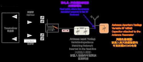
LTE RF front-end (RFFE or Radio Frequency Front End) structure
The industry now has two very different antenna tuning methods:
Tunable Impedance Matching Tuning (TIM)
Antenna Aperture Tuning (AAT)
The use of tunable impedance matching requires a variable matching network between the antenna and the receiver / transmitter. As the frequency changes, the impedance of the antenna changes, and the impedance of the antenna needs to be adjusted back to 50Ω as required by RFFE. This requires a closed loop system to monitor the incident and reflected power or to measure the real and imaginary parts of the antenna impedance. Based on these measurements, the tuning elements of the matching network are adjusted to form a new antenna feed point impedance to optimize power transfer.
As for the antenna aperture tuning technique, a high-Q variable capacitor is placed at a suitable location in the radiating element. The load of the variable capacitance as the frequency changes is dynamically adjusted so that the antenna resonant frequency matches the operating frequency. Matching the resonant frequency and operating frequency helps to keep the antenna’s feedpoint impedance relatively constant over the entire operating range, while a simple fixed network matches the impedance to the feed point target impedance of 50Ω, ensuring that the tuning antenna and the RFFE Between the optimal power transmission.
To better understand how a typical PIFA antenna is implemented, the author will depict the real and imaginary parts of its impedance, and explain how they change with frequency.
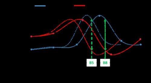
PIFA impedance performance at different frequencies
Figure 3 shows the PIFA antenna frequency is adjusted to 920Mhz (band B8), then reactance as close as possible 0Ω and capacitance as large as possible, about 90Ω. The combination of high resistance and low inductance directly leads to good radiation efficiency – the optimal state of antenna tuning. However, if the PIFA antenna in Fig. 3 operates at 860 MHz (band B5), it is found that the reactance is significantly increased to nearly 60?. The inductance effect of this antenna assembly hoards without radiant energy, thereby reducing the operational efficiency of the antenna. In addition, the antenna is seriously mismatched in the operation of the band B5, reducing the power transfer from the feeder to the low efficiency antenna.
The following explains how two antenna tuning schemes optimize the performance of a PIFA antenna:
The antenna aperture tuning scheme acts to change the load of the variable capacitance, matching the resonant frequency of the antenna with the operating frequency. Resonant frequency adjustment minimizes the impedance of the antenna (close to 0Ω) and maximizes its resistance (close to 90Ω). This allows the antenna to maintain optimum performance at any point in the spectrum, as shown by the dashed curve in Figure 3. In addition, ultra-low loss RF MEMS micro-electromechanical systems (RF MEMS) with less than 0.3 dB insertion loss are now available for antenna aperture tuning techniques, further exploiting antenna radiation, minimizing power loss (hoarded within RFFE) .
The adjustable impedance matching scheme measures the impedance of the antenna and adjusts the feed line to match the corresponding impedance, which optimizes the power conversion from a 50Ω RFFE to a variable load presented by the antenna. However, impedance matching does not prevent the antenna reactance characteristics, which makes the antenna hoarding storage radiation can not make full use of it. In addition, the SOI or BST based components most commonly used in variable impedance matching networks can lead to ohmic losses and generate large (> 1 dB) insertion losses, which further limit tunable impedance matching for power transfer optimization.
This article analyzes the two most common “antenna tuning” techniques today. It is found that the aperture tuning technique exhibits a double advantage over maintaining the resonance of the antenna while simultaneously preventing the feed point mismatch. This reliable, high-performance, and low-loss RF MEMS tuner provides RF engineers and antenna designers with high-efficiency antennas and low-cost RFFEs to manufacture best-in-class smartphone RF equipment.
Hope this article could help you understand the Impedance machine,
Also, Please our website for more Impedance PCB and radio frequency PCB information.

Other PCB products, you may interesting