
PCB EMC simulation:from theory to practice
PCB EMC simulation: from theory to practice
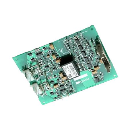
With the increasing complexity and integration of electronic equipment, electromagnetic compatibility (EMC) issues have become increasingly prominent. As the core component of electronic equipment, the EMC performance of PCB directly affects the stability and reliability of the entire device. Traditional EMC design methods mainly rely on experience and rules, which are difficult to meet the stringent requirements of modern electronic equipment for EMC performance. PCB EMC simulation technology came into being and provided a powerful tool for EMC design.
1. Overview of PCB EMC simulation
PCB EMC simulation refers to the use of computer software to simulate and analyze the electromagnetic characteristics of PCB to predict and evaluate its EMC performance. Through simulation, potential EMC problems can be identified and PCB design can be optimized, thereby reducing the number of design iterations, shortening the product development cycle, and reducing development costs.
1.1 The significance of PCB EMC simulation
- Improve design efficiency: Simulation can discover and solve EMC problems in the design stage, avoiding the waste of time and cost caused by later rectification.
- Optimize design scheme: Simulation can compare and evaluate different design schemes, select the best scheme, and improve the EMC performance of PCB.
- Reduce development risk: Simulation can predict the EMC performance of PCB and reduce the risk of EMC problems after the product is launched.
1.2 Classification of PCB EMC simulation
Depending on the simulation object, PCB EMC simulation can be divided into the following categories:
- Signal integrity (SI) simulation: Mainly analyzes the transmission characteristics of high-speed signals on PCB, including reflection, crosstalk, loss, etc.
- Power integrity (PI) simulation: Mainly analyzes the impedance characteristics of the power distribution network (PDN) and evaluates the impact of power supply noise on the circuit.
- Electromagnetic interference (EMI) simulation: Mainly analyzes the electromagnetic radiation generated by PCB and evaluates its interference with other devices.
- Electromagnetic susceptibility (EMS) simulation: Mainly analyzes the resistance of PCB to external electromagnetic interference.
2. PCB EMC simulation process
PCB EMC simulation usually includes the following steps:
2.1 Pre-processing
- Establish simulation model: According to the PCB design file, establish a simulation model containing information such as components, routing, vias, and stacking.
- Set simulation parameters: According to the simulation type and target, set the simulation frequency range, excitation source, boundary conditions and other parameters.
2.2 Simulation solution
- Select simulation algorithm: According to the simulation model and parameters, select a suitable simulation algorithm, such as finite element method (FEM), finite difference time domain method (FDTD), etc.
- Run simulation software: Use simulation software to solve the model and obtain results such as electromagnetic field distribution, S parameters, and radiation field strength.
2.3 Post-processing
- Result analysis: Analyze the simulation results to identify potential EMC problems, such as signal reflection, power supply noise, and electromagnetic radiation.
- Optimize design: According to the simulation results, optimize the PCB design, such as adjusting the trace length, adding decoupling capacitors, changing the stacking structure, etc.
- Verify simulation results: Verify the accuracy of the simulation results through actual tests, and further optimize the simulation model and parameters based on the test results.
3. PCB EMC simulation software
There are many excellent PCB EMC simulation software on the market, such as:
- ANSYS HFSS: High-frequency electromagnetic field simulation software, suitable for EMI/EMS simulation of complex structures.
- CST Studio Suite: Three-dimensional electromagnetic field simulation software, suitable for various types of EMC simulation.
- Cadence Sigrity: Simulation software focusing on signal integrity and power integrity.
- Mentor Graphics HyperLynx: Provides a complete SI/PI simulation solution from schematics to PCB.
4. Key technologies for PCB EMC simulation
4.1 Establishment of simulation model
The accuracy of the simulation model directly affects the reliability of the simulation results. The following factors need to be considered when establishing a simulation model:
- Component model: Use accurate component models, including package models and electrical models.
- Trace model: Consider the geometry, material properties and processing technology of the trace.
- Via model: Consider the structure, size and position of the via.
- Stack structure: Accurately describe the stack structure of the PCB, including the thickness, material properties and dielectric constant of each layer.
4.2 Selection of simulation algorithm
Different simulation algorithms are suitable for different simulation scenarios. Choosing a suitable simulation algorithm can improve simulation efficiency and accuracy.
- Finite element method (FEM): Suitable for electromagnetic field simulation of complex structures, with high calculation accuracy, but large amount of calculation.
- Finite difference time domain method (FDTD): Suitable for broadband electromagnetic field simulation, with high calculation efficiency, but high requirements for meshing.
- Method of moments (MoM): Suitable for electromagnetic field simulation of metal structures, with high calculation efficiency, but difficult to handle complex media.
4.3 Analysis of simulation results
The analysis of simulation results needs to combine EMC theory and practical experience. Common analysis methods include:
- Time domain analysis: Observe signal waveforms and analyze signal integrity issues.
- Frequency domain analysis: Observe spectrum diagrams and analyze electromagnetic interference issues.
- Parameter sweep: Analyze the impact of different parameters on EMC performance.
5. Development trend of PCB EMC simulation
5.1 Improvement of simulation accuracy and efficiency
With the continuous development of computer technology, the accuracy and efficiency of simulation software will continue to improve, and it will be able to handle more complex PCB models and electromagnetic problems.
5.2 Multi-physics coupling simulation
EMC problems often involve the coupling of multiple physical fields, such as electromagnetic fields, thermal fields, structural fields, etc. In the future, PCB EMC simulation will pay more attention to multi-physics coupling simulation to more accurately predict and evaluate EMC performance.
5.3 Application of artificial intelligence technology
Artificial intelligence technology can be used to optimize simulation models, select simulation parameters, analyze simulation results, etc., thereby improving simulation efficiency and accuracy.
Summary
PCB EMC simulation technology is an important tool for EMC design, which can effectively improve design efficiency, optimize design solutions, and reduce development risks. With the continuous development of simulation technology, PCB EMC simulation will play an increasingly important role in electronic equipment design.