
Printed Circuit Board Testing Methods
Introduction
Printed Circuit Boards (PCBs) are the backbone of modern electronics, serving as the platform for interconnecting various electronic components. Given their critical role, ensuring the reliability and functionality of PCBs is paramount. PCB testing is a crucial step in the manufacturing process, aimed at identifying defects, ensuring quality, and guaranteeing that the final product meets the required specifications. This article delves into various PCB testing methods, their principles, advantages, and limitations.
1. Visual Inspection
1.1 Manual Visual Inspection
Manual visual inspection is the most basic form of PCB testing. It involves a technician examining the PCB under magnification to identify visible defects such as solder bridges, missing components, misaligned parts, and scratches. This method is straightforward and cost-effective but is limited by human error and the inability to detect internal or microscopic defects.
1.2 Automated Optical Inspection (AOI)
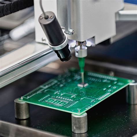
Automated Optical Inspection (AOI) uses high-resolution cameras and sophisticated software to inspect PCBs. The system captures images of the PCB and compares them to a predefined standard. AOI can detect a wide range of defects, including soldering issues, component placement errors, and surface defects. It is faster and more accurate than manual inspection but may struggle with complex or densely populated boards.
2. Electrical Testing
2.1 In-Circuit Testing (ICT)
In-Circuit Testing (ICT) is a comprehensive method that verifies the electrical performance of individual components and their connections on the PCB. ICT uses a bed of nails fixture to make contact with test points on the board. It can measure resistance, capacitance, inductance, and other parameters to identify open circuits, short circuits, and faulty components. ICT is highly accurate but requires custom fixtures, making it expensive and time-consuming to set up.
2.2 Flying Probe Testing
Flying Probe Testing is a non-intrusive method that uses movable probes to test the electrical characteristics of a PCB. Unlike ICT, it does not require a custom fixture, making it more flexible and cost-effective for small production runs or prototypes. Flying probe testers can access both sides of the board and test a wide range of parameters. However, they are slower than ICT and may not be suitable for high-volume production.
2.3 Boundary Scan Testing
Boundary Scan Testing, based on the IEEE 1149.1 standard, is used to test the interconnections between integrated circuits (ICs) on a PCB. It employs a dedicated test access port (TAP) and boundary-scan cells embedded in the ICs to control and observe the signals at the pins. This method is particularly useful for testing complex, high-density boards with limited physical access. Boundary scan testing is highly effective for detecting opens, shorts, and stuck-at faults but requires ICs with built-in boundary-scan capabilities.
3. Functional Testing
3.1 Functional Circuit Test (FCT)
Functional Circuit Test (FCT) evaluates the overall functionality of the PCB by simulating its operating environment. The PCB is powered up, and its performance is measured against the design specifications. FCT can identify issues related to the interaction between components, firmware, and software. It is essential for ensuring that the PCB performs as intended in real-world conditions. However, FCT may not pinpoint the exact location of a defect, requiring additional diagnostic testing.
3.2 Burn-In Testing
Burn-In Testing involves operating the PCB at elevated temperatures and voltages for an extended period to identify early-life failures. This method accelerates the aging process, revealing defects that may not be apparent during initial testing. Burn-in testing is commonly used for high-reliability applications, such as aerospace and medical devices. While effective, it is time-consuming and can stress the components, potentially reducing their lifespan.
4. Environmental Testing
4.1 Thermal Cycling
Thermal Cycling tests the PCB’s ability to withstand temperature variations. The board is subjected to repeated cycles of heating and cooling to simulate real-world conditions. This method can reveal issues related to thermal expansion, solder joint integrity, and material compatibility. Thermal cycling is crucial for applications exposed to extreme temperatures, such as automotive and industrial electronics.
4.2 Vibration and Shock Testing
Vibration and Shock Testing assess the PCB’s durability under mechanical stress. The board is exposed to controlled vibrations and shocks to simulate conditions such as transportation, installation, and operation in harsh environments. This testing can identify weaknesses in solder joints, component mounting, and overall structural integrity. It is particularly important for military, aerospace, and automotive applications.
5. Advanced Testing Methods
5.1 X-Ray Inspection
X-Ray Inspection is a non-destructive method that allows for the examination of internal structures and hidden features of a PCB. It is particularly useful for inspecting solder joints under Ball Grid Array (BGA) packages, vias, and multi-layer boards. X-ray inspection can detect voids, cracks, and misalignments that are not visible through optical methods. However, it requires specialized equipment and expertise, making it more expensive and less accessible than other methods.
5.2 Acoustic Microscopy
Acoustic Microscopy uses high-frequency sound waves to detect defects within the PCB. The sound waves are transmitted through the board, and the reflections are analyzed to identify anomalies such as delamination, cracks, and voids. This method is highly effective for inspecting multi-layer boards and identifying internal defects. However, it is complex and requires specialized equipment and skilled operators.
6. Conclusion
PCB testing is a critical aspect of the manufacturing process, ensuring the reliability, functionality, and quality of the final product. Various testing methods, from basic visual inspection to advanced techniques like X-ray inspection and acoustic microscopy, offer different levels of insight into the PCB’s condition. Each method has its advantages and limitations, and the choice of testing method depends on factors such as the complexity of the board, production volume, and specific application requirements.
As technology continues to advance, PCB testing methods are evolving to meet the demands of increasingly complex and high-density designs. The integration of automated systems, artificial intelligence, and machine learning is enhancing the accuracy, speed, and efficiency of PCB testing. By employing a combination of testing methods, manufacturers can ensure that their PCBs meet the highest standards of quality and reliability, ultimately leading to the production of robust and dependable electronic devices.