
Flexible PCB Failure Modes: Causes, Mechanisms, and Prevention Strategies
Introduction
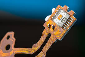
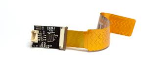
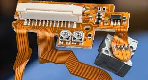
Flexible printed circuit boards (Flex PCBs) have become essential components in modern electronics, enabling innovative product designs in industries ranging from consumer electronics to medical devices and aerospace systems. Unlike traditional rigid PCBs, flex circuits can bend, fold, and twist to fit into compact or irregularly shaped spaces. However, this very flexibility also introduces unique failure modes that engineers must understand and address during design, manufacturing, and application.
This comprehensive article examines the most common failure modes of flexible PCBs, analyzing their root causes, failure mechanisms, and effective prevention strategies. By understanding these failure modes, engineers can improve product reliability, extend service life, and reduce costly field failures.
1. Mechanical Stress-Induced Failures
1.1 Conductor Fracture
One of the most prevalent failure modes in flexible PCBs is conductor fracture caused by repeated mechanical stress. This typically occurs at:
- Bend areas where the circuit undergoes frequent flexing
- Transition zones between rigid and flexible sections
- Locations near connectors or components
Failure Mechanism:
Copper traces in flex circuits work-harden with repeated bending, becoming increasingly brittle until microcracks form and propagate. Eventually, these cracks lead to complete trace separation.
Prevention Strategies:
- Implement proper bend radius guidelines (typically 6-10x material thickness for dynamic flexing)
- Use rolled annealed copper instead of electrodeposited copper for better fatigue resistance
- Position conductors in the neutral bending axis where strain is minimized
- Utilize curved traces instead of right-angle turns to distribute stress
1.2 Delamination
Delamination refers to the separation of different material layers within the flex PCB stackup, particularly between:
- Copper conductors and polyimide substrate
- Coverlay and conductor layers
- Stiffener attachment interfaces
Failure Mechanism:
Mechanical stress creates shear forces that overcome the adhesive strength between layers. Contamination during manufacturing or moisture ingress can accelerate this process.
Prevention Strategies:
- Specify high-performance adhesives with appropriate glass transition temperatures
- Ensure proper surface preparation before lamination
- Implement robust cleaning processes to remove contaminants
- Use appropriate pressure and temperature during lamination
2. Environmental Stress Failures
2.1 Thermal Cycling Damage
Flex circuits often experience wide temperature variations in operation, leading to:
- Coefficient of thermal expansion (CTE) mismatch stresses
- Material degradation at temperature extremes
- Interconnect failures
Failure Mechanism:
Different materials in the flex PCB assembly expand and contract at different rates during temperature cycles, creating mechanical stresses that can fracture conductors or weaken bonds.
Prevention Strategies:
- Select materials with matched CTE where possible
- Incorporate stress-relief features in design
- Use high-temperature stable adhesives and substrates
- Consider the entire system’s thermal expansion characteristics
2.2 Moisture and Chemical Degradation
Exposure to humidity, liquids, or corrosive chemicals can cause:
- Metal corrosion
- Polymer swelling
- Reduced dielectric strength
- Accelerated delamination
Failure Mechanism:
Moisture penetrates the polyimide substrate or through microcracks in coverlay, leading to oxidation of copper traces or weakening of material interfaces.
Prevention Strategies:
- Specify moisture-resistant materials (e.g., liquid crystal polymer for harsh environments)
- Apply conformal coatings for additional protection
- Implement proper sealing at edges and terminations
- Use corrosion-resistant finishes like ENIG or immersion silver
3. Electrical Failure Modes
3.1 Conductor Wear and Thinning
Dynamic flexing applications can experience gradual conductor wear, leading to:
- Increased resistance
- Current carrying capacity reduction
- Eventual open circuits
Failure Mechanism:
Friction between layers during flexing causes abrasive wear of copper traces, particularly at bend locations.
Prevention Strategies:
- Specify appropriate copper weights for expected current loads
- Incorporate wear-resistant coatings
- Minimize relative motion between layers
- Consider alternative conductor materials like silver ink for high-flex applications
3.2 Dielectric Breakdown
Electrical insulation failures can occur due to:
- Material thinning in bend areas
- Presence of contaminants or voids
- Partial discharge in high-voltage applications
Failure Mechanism:
Reduced dielectric thickness or material defects create paths for current leakage or arcing.
Prevention Strategies:
- Maintain adequate dielectric thickness, especially in bend areas
- Specify materials with appropriate dielectric strength
- Implement thorough electrical testing protocols
- Use corona-resistant materials for high-voltage applications
4. Manufacturing-Related Failures
4.1 Etching Defects
Improper etching processes can lead to:
- Over-etched conductors (reduced cross-section)
- Under-etched traces (potential shorts)
- Uneven trace edges (stress concentrators)
Failure Mechanism:
Inconsistent etching creates weak points in conductors that are more susceptible to mechanical and electrical failure.
Prevention Strategies:
- Tightly control etching parameters (time, temperature, chemistry)
- Implement automated optical inspection (AOI)
- Use additive processes for fine features when possible
4.2 Lamination Voids
Voids or bubbles in laminated layers can cause:
- Reduced mechanical strength
- Moisture ingress paths
- Localized current crowding
Failure Mechanism:
Trapped air or contaminants prevent proper bonding between layers, creating weak points.
Prevention Strategies:
- Optimize lamination pressure and temperature profiles
- Ensure proper material handling to prevent contamination
- Use vacuum lamination processes for critical applications
5. Design-Related Failures
5.1 Improper Bend Radius
Designs that violate minimum bend radius guidelines often experience:
- Immediate conductor cracking
- Reduced fatigue life
- Accelerated delamination
Failure Mechanism:
Excessive bending creates strains beyond the material’s elastic limits, causing permanent damage.
Prevention Strategies:
- Follow manufacturer’s bend radius recommendations
- Use bend radius calculators that consider material stackup
- Implement strain relief features in high-flex areas
5.2 Poor Transition Design
Abrupt transitions between rigid and flexible sections can lead to:
- Stress concentration
- Cracking near component terminations
- Solder joint failures
Failure Mechanism:
Mechanical stress becomes concentrated at sharp transitions rather than being distributed gradually.
Prevention Strategies:
- Use tapered stiffeners
- Implement graduated thickness transitions
- Add reinforcement at critical transition points
6. Application-Specific Failure Modes
6.1 Dynamic Flexing Applications
Products requiring continuous flexing (e.g., folding smartphones, robotic joints) face unique challenges:
- Accelerated fatigue failure
- Wear particle generation
- Interlayer adhesion loss
Mitigation Strategies:
- Use ultra-thin copper with high elongation properties
- Incorporate wear-resistant interlayer coatings
- Design with redundant conductors for critical signals
6.2 High-Reliability Applications
Medical implants, aerospace, and automotive systems demand exceptional reliability:
- Long-term material stability concerns
- Creep and stress relaxation effects
- Performance under extreme environments
Mitigation Strategies:
- Select high-performance materials (e.g., Upilex polyimide)
- Implement accelerated life testing protocols
- Design with generous safety margins
Failure Analysis Techniques
Effective failure analysis is crucial for identifying and addressing flex PCB failures:
- Visual Inspection: Low-power microscopy for obvious defects
- X-ray Imaging: Reveals internal structure and hidden defects
- Cross-Sectioning: Examines material interfaces and plating quality
- SEM/EDS: Identifies fracture modes and material composition
- Thermal Imaging: Locates hot spots and current crowding
- Electrical Testing: Verifies continuity and insulation resistance
Prevention and Reliability Enhancement
Comprehensive reliability improvement requires:
- Design for Reliability (DfR): Incorporate reliability considerations from initial concept
- Material Selection: Choose materials matched to application requirements
- Process Control: Implement rigorous manufacturing quality systems
- Testing and Validation: Perform accelerated life testing and environmental stress screening
- Application-Specific Considerations: Tailor solutions to actual use conditions
Conclusion
Flexible PCB failure modes present unique challenges that require specialized knowledge to address effectively. By understanding the mechanical, environmental, electrical, and manufacturing-related failure mechanisms discussed in this article, engineers can develop more reliable flexible circuit solutions. Successful implementation requires a systems approach that considers material selection, design optimization, manufacturing process control, and application-specific requirements.
As flexible electronics continue to evolve with emerging technologies like stretchable circuits and printed electronics, the industry must continue to advance its understanding of failure mechanisms and develop new mitigation strategies. Through continued research, improved materials, and refined design practices, the reliability of flexible PCBs will keep pace with their expanding range of applications in modern electronic systems.