
Skip to content
Andwin Circuits
  • Home
  • ProductsExpand
    • HDI multilayer PCB
    • Rigid Flex PCB
    • Flex pcb
    • Special PCBExpand
      • High Frequency PCBExpand
        • Rogers RO4350B PCB
        • Rogers RO4003 pcb
        • Rogers RO3003 PCB
        • Rogers 5880 PCB
        • DICLAD 527 PCB
        • Taconic TLX series
        • Taconic TLX-8 RF PCB
        • Taconic TLX-9 RF PCB
      • High speed pcbExpand
        • Megtron 6 High Speed PCB
        • TU-872 SLK Sp High Speed
      • High TG PCBExpand
        • SHENGYI SH260 PCB
        • ISOLA 370HR PCB
        • ISOLA IS410 PCB
        • ISOLA IS420 PCB
      • Heavy copper PCB
      • Copper coin pcb
      • Copper inlay PCB
    • Metal Core PCBExpand
      • Copper core pcb
      • Aluminum PCB
      • 2 Layers Aluminum PCB
      • Direct thermal MCPCB
      • 2 Layers Direct Thermal
    • Ceramic PCBExpand
      • DPC ceramic PCB
      • DBC ceramic PCB
      • Thick film Ceramic PCB
      • Al2O3 Alumina PCB
      • AIN ALN ceramic PCB
      • IGBT Ceramic PCB
  • ServiceExpand
    • PCB Assembly
    • Quick turn PCB assembly
    • PCBA conformal coating
  • IndustryExpand
    • Telecommunication
    • IoT and Wireless
    • Industrial Control
    • Thermal management
    • Power and Energy
    • IC test board
    • Automative
    • Medical
  • CapabilityExpand
    • Rigid PCB
    • Rigid flex PCB
    • Metal core PCB
    • PCB Assembly
  • TechnologyExpand
    • Blogs
    • Via in pad
    • PCB E-test
    • PCB stack up
    • MCPCB panelization
    • Controlled impedance PCB
  • AboutExpand
    • About us
    • Certification
    • Factory Tour
  • Contact
Andwin Circuits
Home / Why Crystal Oscillators Should Not Be Placed Near PCB Edges

Why Crystal Oscillators Should Not Be Placed Near PCB Edges

ByGrace May 19, 2025May 19, 2025

Abstract

Crystal oscillators (XTALs) are critical components in electronic circuits, providing precise clock signals for microcontrollers, processors, and communication modules. Their placement on a printed circuit board (PCB) significantly impacts performance, signal integrity, and electromagnetic compatibility (EMC). One key design rule is to avoid placing crystal oscillators near PCB edges. This article explores the reasons behind this guideline, covering mechanical stability, signal integrity, EMI susceptibility, thermal effects, and manufacturing considerations.

1. Introduction

Crystal oscillators generate stable frequencies essential for digital systems. Their performance depends not only on the crystal itself but also on PCB layout. Placing a crystal near the board edge can introduce multiple issues, including increased susceptibility to noise, mechanical stress, and electromagnetic interference (EMI). This article examines why PCB designers should avoid edge placement for crystal oscillators.

2. Mechanical Stability and Vibration

2.1. Susceptibility to Mechanical Stress

PCBs near edges are more exposed to mechanical stress during:

  • Assembly and handling (e.g., depaneling, soldering, or mounting).
  • Operation (e.g., vibrations in automotive or industrial applications).

Crystals are sensitive to mechanical stress, which can alter their resonant frequency or even cause cracks, leading to failure.

2.2. Depaneling Risks

If a PCB is panelized (multiple boards manufactured together), depaneling (cutting individual boards) near a crystal can induce stress, affecting its performance.
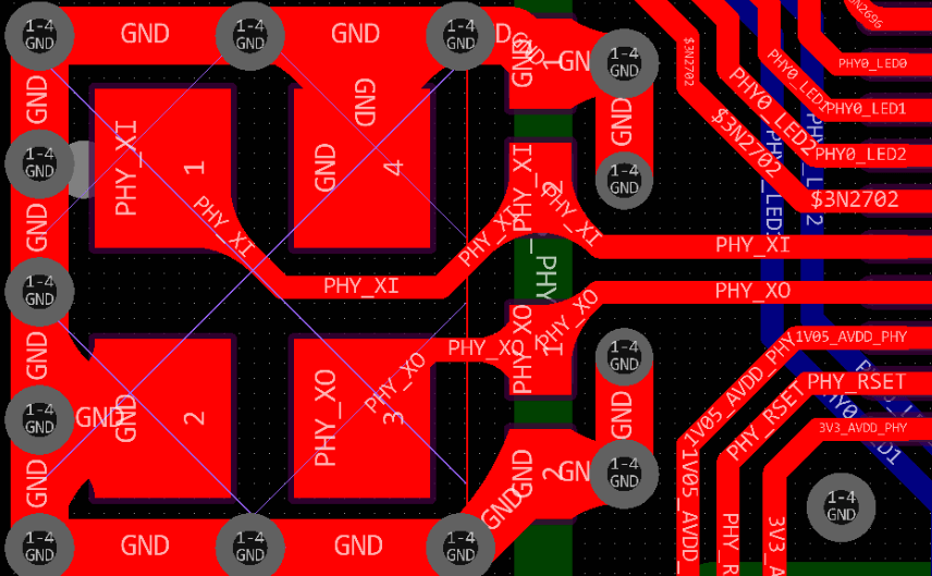
Contact us for PCB quote now |

3. Signal Integrity and Noise

3.1. Increased Susceptibility to EMI

  • PCB edges are more exposed to external electromagnetic interference (e.g., from power supplies, RF sources, or nearby devices).
  • The crystal’s traces act as antennas, picking up noise, which can distort clock signals.

3.2. Crosstalk and Grounding Issues

  • Edge placement may lead to improper grounding, increasing loop inductance and noise coupling.
  • Nearby high-speed signals (e.g., USB, HDMI) can induce crosstalk, degrading clock accuracy.

3.3. Parasitic Capacitance and Impedance Mismatch

  • The lack of a continuous ground plane near edges increases parasitic capacitance, altering crystal load capacitance and frequency stability.

4. Thermal Effects

4.1. Uneven Temperature Distribution

  • PCB edges experience more temperature fluctuations due to:
  • Heat dissipation differences (less copper for heat spreading).
  • Exposure to ambient conditions (e.g., airflow, external heat sources).
  • Crystals are temperature-sensitive; frequency drift can occur if thermal conditions vary.

4.2. Soldering and Reflow Concerns

  • Edge components may experience uneven heating during reflow, leading to poor solder joints or thermal stress on the crystal.

5. Manufacturing and Assembly Challenges

5.1. PCB Warpage and Flexing

  • Board edges are more prone to warping during manufacturing or operation, stressing the crystal.

5.2. Soldering and Rework Difficulties

  • Edge components are harder to inspect and rework, increasing defect risks.

5.3. Compliance with Design Guidelines

  • IPC and industry standards recommend keeping sensitive components (like crystals) away from edges to ensure reliability.
Contact us for PCB quote now |

6. Best Practices for Crystal Placement

To mitigate these issues, follow these PCB layout guidelines:

6.1. Optimal Placement

  • Place the crystal near the IC it drives (minimizing trace length).
  • Ensure a solid ground plane beneath the crystal.

6.2. Proper Shielding and Routing

  • Use guard rings or ground vias to reduce EMI.
  • Keep high-speed signals away from crystal traces.

6.3. Mechanical Considerations

  • Avoid placing crystals near mounting holes or board cutouts.
  • Use strain relief if the PCB is subject to vibration.

7. Conclusion

Placing a crystal oscillator near a PCB edge introduces multiple risks, including mechanical stress, EMI susceptibility, thermal instability, and manufacturing challenges. By following best practices—keeping crystals centrally located, ensuring proper grounding, and minimizing noise coupling—designers can enhance signal integrity and system reliability. Adhering to these guidelines ensures robust performance in applications ranging from consumer electronics to industrial systems.

Contact us for PCB quote now |
Post Tags: #aluminum clad pcb#aluminum core pcb#aluminum pcb#assemble pcb#Why Crystal Oscillators Should Not Be Placed Near PCB Edges

Post navigation

Previous Previous
Dark and Granular Solder Joints on PCBs: Causes, Implications, and Solutions
NextContinue
Types of Resistors in PCB Design

Search

Search

Products

  • HDI Multilayer PCB
  • Rigid Flex PCB
  • Flex pcb
  • High Frequency PCB
  • High speed pcb
  • Heavy copper PCB
  • Metal Core PCB
  • Ceramic PCB

Address

Andwin Circuits Co.,Limited
Email: sales@andwinpcb.com
Tel: +86 755 2832 9394
Fax:+86 755 2992  6717
ADD:1-2F-1217,HouDeQun Industrial park,
NanTing RD NO.56,ShaJing,BaoAn,Shenzhen 518104,GuangDong,China

Products

  • HDI Multilayer PCB
  • Rigid Flex PCB
  • Flex pcb
  • High Frequency PCB
  • High speed pcb
  • Heavy copper PCB
  • Metal Core PCB
  • Ceramic PCB

Technology

  • Blogs
  • Via in pad
  • PCB E-test
  • PCB stack up
  • Metal core PCB panelization
  • Controlled impedance PCB

CERTIFICATION

Certification >>


Copyright© 2003 - 2026 Andwin | All Rights Reserved | Powered by Andwin

Scroll to top
  • Home
  • Products
    • HDI multilayer PCB
    • Rigid Flex PCB
    • Flex pcb
    • Special PCB
      • High Frequency PCB
        • Rogers RO4350B PCB
        • Rogers RO4003 pcb
        • Rogers RO3003 PCB
        • Rogers 5880 PCB
        • DICLAD 527 PCB
        • Taconic TLX series
        • Taconic TLX-8 RF PCB
        • Taconic TLX-9 RF PCB
      • High speed pcb
        • Megtron 6 High Speed PCB
        • TU-872 SLK Sp High Speed
      • High TG PCB
        • SHENGYI SH260 PCB
        • ISOLA 370HR PCB
        • ISOLA IS410 PCB
        • ISOLA IS420 PCB
      • Heavy copper PCB
      • Copper coin pcb
      • Copper inlay PCB
    • Metal Core PCB
      • Copper core pcb
      • Aluminum PCB
      • 2 Layers Aluminum PCB
      • Direct thermal MCPCB
      • 2 Layers Direct Thermal
    • Ceramic PCB
      • DPC ceramic PCB
      • DBC ceramic PCB
      • Thick film Ceramic PCB
      • Al2O3 Alumina PCB
      • AIN ALN ceramic PCB
      • IGBT Ceramic PCB
  • Service
    • PCB Assembly
    • Quick turn PCB assembly
    • PCBA conformal coating
  • Industry
    • Telecommunication
    • IoT and Wireless
    • Industrial Control
    • Thermal management
    • Power and Energy
    • IC test board
    • Automative
    • Medical
  • Capability
    • Rigid PCB
    • Rigid flex PCB
    • Metal core PCB
    • PCB Assembly
  • Technology
    • Blogs
    • Via in pad
    • PCB E-test
    • PCB stack up
    • MCPCB panelization
    • Controlled impedance PCB
  • About
    • About us
    • Certification
    • Factory Tour
  • Contact
Search