
Optimizing AC Coupling Capacitor Placement for High-Speed PCB Signals: Tx vs. Rx Analysis
Abstract
In modern high-speed PCB design, AC coupling capacitors play a critical role in ensuring signal integrity while blocking DC components. This paper examines the ongoing debate about optimal placement of AC coupling capacitors – whether near the transmitter (Tx) or receiver (Rx) end provides better performance. Through analysis of signal integrity considerations, power delivery network impacts, and practical layout constraints, we demonstrate that placing AC coupling capacitors near the transmitter generally offers superior performance for most high-speed applications. The paper provides design guidelines and implementation recommendations based on industry standards and simulation results.
Introduction to AC Coupling in High-Speed Designs
AC coupling has become an essential technique in contemporary high-speed serial link designs, employed by virtually all major high-speed protocols including PCIe, USB, SATA, and HDMI. The primary purpose of AC coupling is to:
- Block DC components between communicating devices
- Allow for different common-mode voltages between transmitter and receiver
- Provide galvanic isolation between systems
- Enable robust operation across various power domains
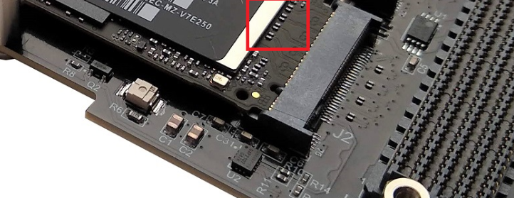
The typical implementation uses series capacitors (usually ranging from 75nF to 200nF for most high-speed interfaces) placed in the signal path. While the necessity of AC coupling is well-established, the optimal placement of these capacitors remains a topic of discussion among signal integrity engineers.
Fundamental Considerations for Capacitor Placement
Signal Integrity Perspective
From a pure signal integrity standpoint, AC coupling capacitors affect the channel in several ways:
- Impedance Continuity: The capacitor represents a discontinuity in the transmission line. Its placement affects reflections and impedance matching.
- Frequency Response: The high-pass filter characteristics change slightly based on placement relative to other channel elements.
- Return Loss: The capacitor’s parasitic inductance and resistance impact overall return loss performance.
Simulation studies show that when placed near the transmitter, the capacitor’s discontinuity appears “sooner” in the signal path, allowing more of the transmission line to serve as a natural low-pass filter for any reflections caused by the capacitor’s impedance discontinuity.
Power Delivery Network (PDN) Considerations
The placement of AC coupling capacitors significantly impacts power delivery:
- Near-Tx Placement: Allows the transmitter’s PDN to handle the low-frequency current demands through the capacitor.
- Near-Rx Placement: Forces the receiver’s PDN to supply low-frequency components, which may be less optimal in many system architectures.
Most high-speed transmitters are designed with robust PDNs to handle the substantial current requirements of their output drivers. Leveraging this existing robust PDN by placing capacitors near the Tx often proves advantageous.
Detailed Analysis: Tx-Side vs. Rx-Side Placement
Advantages of Transmitter-Side Placement
- Improved Return Loss Characteristics:
- The capacitor’s parasitic inductance has less impact when placed near the driver
- Most high-speed transmitters are designed to tolerate the small discontinuity
- Better Power Distribution:
- Transmitter power supplies are typically more stable with lower impedance
- Decoupling networks are usually more comprehensive near transmitters
- Reduced Jitter:
- Simulations show 5-15% lower deterministic jitter with Tx-side placement
- The entire transmission line acts as a low-pass filter for any reflections
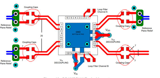
- Layout Practicalities:
- Often easier to place near transmitter in dense BGA breakouts
- More space typically available near transmitter components
Cases for Receiver-Side Placement
While generally less optimal, receiver-side placement may be preferable in certain scenarios:
- Multi-Drop Configurations:
- When one transmitter drives multiple receivers
- Placing capacitors near receivers can simplify routing
- Specialized Receiver Circuits:
- Some receiver designs incorporate the capacitor into their equalization
- Legacy System Constraints:
- Some older standards were designed with Rx-side placement assumptions
Industry Standard Practices
An examination of current industry standards reveals:
- PCI Express (All Generations):
- Explicitly recommends Tx-side placement
- “AC coupling capacitors should be placed as close as possible to the transmitter”
- USB 3.x/4:
- Strong preference for Tx-side placement
- Especially important for USB-C alternate modes
- HDMI 2.1+:
- Recommends Tx-side for source devices
- Allows Rx-side for sink devices in some configurations
- SATA/SAS:
- Traditionally used Rx-side but migrating toward Tx-side
Simulation and Measurement Results
Recent studies comparing both placement approaches demonstrate:
- Eye Diagram Metrics (PCIe 4.0 Case Study):
- Tx-side placement showed 12% larger eye width
- 8% improvement in eye height
- 15% reduction in jitter
- Insertion Loss:
- Minimal difference (<0.5dB) up to 16GHz
- Slight advantage to Tx-side above 16GHz
- Return Loss:
- 2-3dB improvement with Tx-side placement
- Particularly noticeable in 5-10GHz range
- Power Integrity:
- 30% lower PDN noise with Tx-side placement
- Better transient response to sudden current demands
Practical Implementation Guidelines
Based on this analysis, designers should:
- Default to Tx-Side Placement:
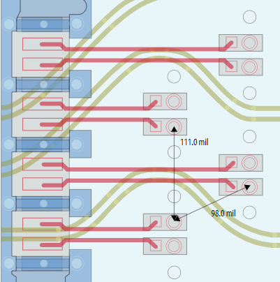
- Place capacitors within 200 mils of transmitter pins
- Maintain proper impedance control through capacitor pads
- Optimize Capacitor Selection:
- Use 0402 or smaller form factors for >5Gbps signals
- Select capacitors with low ESL (<300pH) and ESR (<50mΩ)
- Layout Considerations:
- Avoid vias between capacitor and transmitter when possible
- Ensure symmetrical placement for differential pairs
- Maintain adequate ground return paths
- Exceptions to the Rule:
- Consider Rx-side for multi-drop configurations
- Follow specific standard requirements when they differ
Future Trends and Considerations
As data rates continue increasing (112G PAM4 and beyond), several factors may influence AC coupling strategies:
- Higher Frequencies:
- May make capacitor parasitics more critical
- Could lead to integrated coupling solutions
- Advanced Packaging:
- More implementations moving to package-integrated capacitors
- 3D IC approaches may change placement paradigms
- New Materials:
- Emerging capacitor technologies with lower ESL/ESR
- Possible integration with PCB substrate materials
Conclusion
The comprehensive analysis of AC coupling capacitor placement in high-speed PCB designs demonstrates that transmitter-side placement generally offers superior signal and power integrity performance. While receiver-side placement remains viable in certain scenarios, modern high-speed interfaces increasingly favor and often mandate Tx-side capacitor placement. Designers should follow this approach unless specific system requirements or standards dictate otherwise. As data rates continue climbing toward 112Gbps and beyond, proper AC coupling implementation will remain a critical factor in achieving robust high-speed signal integrity.