
Ionic Contamination Testing of PCB Boards: Methods and Importance
Abstract
Printed Circuit Boards (PCBs) are fundamental components in modern electronics, and their reliability is critical to the performance of electronic devices. Ionic contamination on PCB surfaces can lead to electrochemical migration, corrosion, and eventual failure of the board. This paper explores the chemical testing methods for detecting ionic contamination on PCBs, including the principles, procedures, and industry standards such as IPC-TM-650. The discussion covers the importance of contamination control, common sources of ionic residues, and the impact on PCB performance. Finally, the paper highlights best practices for minimizing ionic contamination in PCB manufacturing and assembly.
1. Introduction
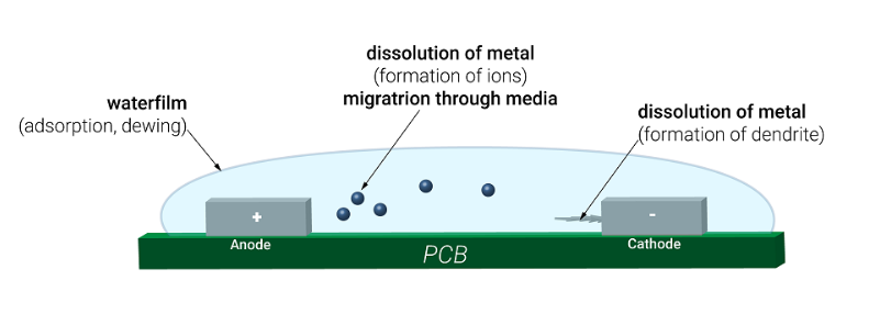
PCBs are exposed to various contaminants during manufacturing, handling, and assembly processes. Ionic contamination—caused by residues from fluxes, plating chemicals, fingerprints, and environmental exposure—can severely impact the electrical performance and long-term reliability of PCBs. When ionic residues combine with moisture, they create conductive paths that can lead to dendritic growth, short circuits, and corrosion. Therefore, ionic contamination testing is essential to ensure PCB quality and reliability.
This paper focuses on the chemical testing methods used to detect and quantify ionic contamination, including resistivity of solvent extract (ROSE) testing, ion chromatography (IC), and surface insulation resistance (SIR) testing. These methods help manufacturers identify contamination sources and implement corrective measures.
2. Sources of Ionic Contamination in PCBs
Ionic contamination originates from multiple stages of PCB fabrication and assembly, including:
- Flux residues from soldering processes (e.g., no-clean, water-soluble, or rosin-based fluxes).
- Etching and plating chemicals (e.g., acids, alkalis, and metal ions from copper plating).
- Human handling (e.g., sweat and fingerprints containing sodium, chloride, and potassium ions).
- Environmental exposure (e.g., dust, humidity, and airborne contaminants).
- Cleaning agents (e.g., improper rinsing leaves detergent residues).
These contaminants can remain on the PCB surface or within layers, leading to electrochemical failures under humid or high-voltage conditions.
3. Chemical Testing Methods for Ionic Contamination
3.1 Resistivity of Solvent Extract (ROSE) Testing
The ROSE test (per IPC-TM-650 Method 2.3.25) is the most widely used method for detecting ionic contamination. It measures the resistivity of a solvent extract from the PCB surface.
Procedure:
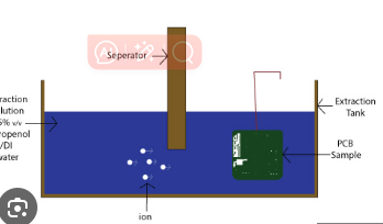
- The PCB is immersed in a 75% isopropyl alcohol (IPA) and 25% deionized (DI) water solution.
- The solution is agitated to dissolve ionic residues.
- The resistivity of the solution is measured using a conductivity meter.
- The contamination level is calculated in μg/cm² of sodium chloride (NaCl) equivalents.
Advantages:
- Fast and cost-effective.
- Suitable for batch testing in production environments.
Limitations:
- Does not identify specific ion types.
- Less sensitive to certain organic residues.
3.2 Ion Chromatography (IC)
Ion chromatography provides a detailed analysis of ionic species present on a PCB. It separates and quantifies individual anions (e.g., Cl⁻, Br⁻, SO₄²⁻) and cations (e.g., Na⁺, K⁺, Cu²⁺).
Procedure:
- The PCB is rinsed with ultra-pure water to collect ionic residues.
- The solution is injected into an ion chromatograph.
- Ions are separated via a chromatographic column and detected by conductivity.
Advantages:
- Identifies specific contaminants for targeted cleaning.
- High sensitivity (detects ppm/ppb levels).
Limitations:
- More expensive and time-consuming than ROSE testing.
- Requires specialized equipment and expertise.
3.3 Surface Insulation Resistance (SIR) Testing
SIR testing (IPC-TM-650 Method 2.6.3.7) evaluates the long-term effects of ionic contamination under controlled humidity and temperature.
Procedure:
- A test pattern (comb structure) is fabricated on the PCB.
- The board is exposed to 85°C and 85% relative humidity.
- Electrical resistance is monitored over time (typically 7-14 days).
Advantages:
- Simulates real-world operating conditions.
- Detects electrochemical migration risks.
Limitations:
- Time-consuming compared to ROSE and IC.
- Requires dedicated test boards.
4. Industry Standards and Acceptable Limits
Several standards define acceptable contamination levels:
- IPC-J-STD-001: Limits ionic contamination to ≤1.56 μg/cm² NaCl equivalent for high-reliability electronics.
- IPC-6012: Specifies cleanliness requirements for rigid PCBs.
- MIL-STD-883: Military-grade requirements for harsh environments.
Exceeding these limits may require additional cleaning or rejection of the PCB batch.
5. Best Practices for Minimizing Ionic Contamination
To reduce ionic contamination risks, manufacturers should:
- Implement strict cleaning processes (e.g., ultrasonic cleaning, DI water rinsing).
- Use low-residue fluxes and solder pastes.
- Control humidity in storage and assembly areas.
- Enforce glove use to prevent fingerprint contamination.
- Regularly monitor cleanliness using ROSE or IC testing.
6. Conclusion
Ionic contamination testing is crucial for ensuring PCB reliability in electronic devices. The ROSE test provides a quick screening method, while ion chromatography offers detailed contamination analysis. SIR testing helps assess long-term reliability under humid conditions. By adhering to industry standards and implementing contamination control measures, manufacturers can enhance PCB performance and longevity.
Future advancements may include automated inline testing and more sensitive detection techniques to further improve contamination control in PCB manufacturing.