What files are there for PCB temperature curve system
A classic PCB temperature curve system consists of the following components:
· Data collection curve meter, which passes through the middle of the furnace and collects temperature information from the PCB.
· Thermocouples, which are attached to key components on the PCB and then connected to the accompanying curve meter.
· Thermal protection, which protects the curve meter from being heated by the furnace.
· Software program, which allows the collected data to be viewed in a format to quickly determine soldering results and/or find out-of-control trends before out-of-control adversely affects the final PCB product.
Thermocouples
The most commonly used in the electronics industry is the K-type thermocouple. There are various techniques for attaching thermocouples to components on the PCB. The method used depends on the type of PCB being processed, as well as the user’s preference.
Thermocouple attachment
High temperature solder, which provides a strong connection to the PCB. This method is usually used for operations where a dedicated reference board can be sacrificed for profiling and process verification. Care should be taken to ensure the minimum amount of solder is applied to avoid affecting the profile.
Adhesives, which can be used to secure the thermocouple to the PCB. The use of adhesives usually results in a rigid physical connection of the thermocouple to the assembly. Disadvantages include the possibility that the adhesive may fail during heating and leave residue on the assembly when removed after profiling. Also, care should be taken to use the minimum amount of adhesive, as the added thermal mass may affect the results of the temperature profile.
Kapton or aluminum tape, which is the easiest to use, but the least reliable method of attachment. Temperature profiling using tape often shows very jagged curves because the thermocouple junction lifts from the contact surface during heating. The ease of use and the lack of residue that can affect the assembly make Kapton or aluminum tape a popular method.
Pressure-type thermocouples, which clamp to the edge of the board and use a spring force to firmly contact and secure the thermocouple junction to the assembly being profiled. Pressure probes are quick and easy to use and are non-destructive to the PCB.
Thermocouple Placement
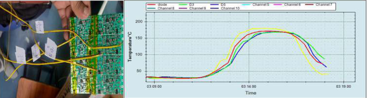
Because the outer edges and corners of an assembly heat faster than the center, and components with greater thermal mass heat more fully than components with less thermal mass, at least four thermocouple placements are recommended. Place one thermocouple at an edge or corner of the assembly, one on a small component, another in the center of the board, and a fourth on a larger mass component. Additional thermocouples may be added at other parts of interest on the board, or at components that are most at risk of thermal shock or thermal damage.
Reading and Estimating Temperature Profile Data
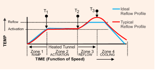
Solder paste manufacturers typically have a recommended temperature profile specific to their solder paste formulations. The manufacturer’s recommendations should be used to determine the best profile for a particular process and compared to the actual assembly results. Steps may then be taken to change machine settings to achieve the best results for a particular assembly (Figure 3).
For PCB assembly manufacturers, new tools are now available that make it easy to design a target profile for a specific combination of solder paste and reflow oven. Once designed, this target profile can be automatically run in the reflow oven by simply calling up the machine operator for this specific PCB assembly.
When to Profile
Profiling is particularly useful when starting a new assembly. Oven settings must be determined to optimize the process for high quality results. As a diagnostic tool, a profiler can be invaluable in helping to identify processes with poor yields and/or high rework.
Profiling can reveal inappropriate oven settings or ensure that those settings are appropriate for the assembly. Many companies or plants profile on standard reference boards or use a quality control profiler on the machine daily. Some plants profile at the beginning of each shift to verify oven operation and avoid potential problems before they occur. These profiles can be stored as a hard copy or in electronic format and used as part of an ISO program or to perform statistical process control (SPC) of machine performance over time.
Assemblies used for profiling should be handled with care. The assembly may degrade due to improper handling or repeated exposure to reflow temperatures. Profiled boards may delaminate over time and thermocouple attachments may loosen, which should be expected and the profiling equipment should be inspected before each run is compromised. The key is to ensure that the measurement equipment is capable of producing accurate results.
Classic PCB Temperature Profiling vs. Machine Quality Control Profiling
While the most common type of temperature profiling involves using an on-the-fly profiler and thermocouples to monitor the temperature of PCB components, temperature profiling is also used to ensure that reflow ovens are consistently operating at optimal settings. A variety of built-in machine temperature profilers are available that provide routine monitoring of key reflow oven parameters, including air temperature, heat flux and conveyor speed. These instruments also provide the opportunity to quickly identify any out-of-control trends before they affect the quality of the final PCB assembly.