Rogers High-Frequency Board Material Selection Guide: RF PCB Dielectric Constant Matching
Selecting the right high-frequency PCB material can make or break your RF design. Rogers Corporation materials have become the gold standard for applications ranging from 5G base stations to automotive radar systems, but choosing between RO4003C, RO4350B, RO5880, and other variants requires understanding how dielectric constant (Dk) matching impacts your circuit performance.
This guide walks you through the critical factors in Rogers material selection, helping you match substrate properties to your RF design requirements while avoiding costly mistakes.
Understanding Dielectric Constant in RF PCB Design
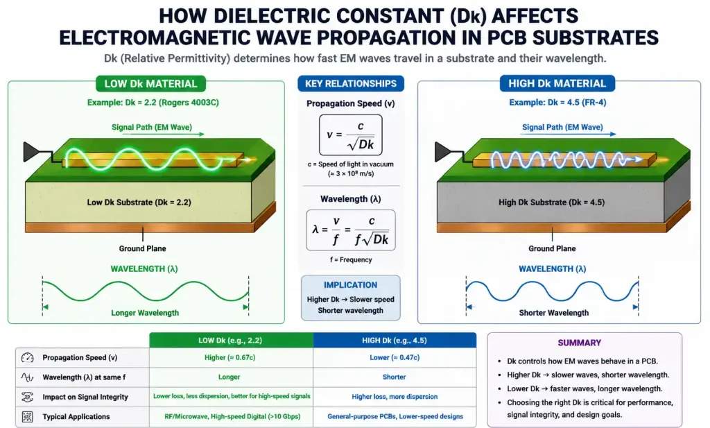
The dielectric constant (Dk or εr) fundamentally determines how electromagnetic signals propagate through your PCB substrate. In RF and microwave circuits, Dk directly affects signal velocity, trace impedance, and the physical dimensions of resonant structures.
When designing RF circuits, the dielectric constant serves two critical functions:
Impedance Control: The characteristic impedance of transmission lines depends on the square root of the dielectric constant. A Dk of 3.5 versus 4.5 requires significantly different trace geometries to achieve the same 50Ω impedance.
Physical Dimensions: Lower Dk values increase the effective wavelength inside the substrate, which means larger physical structures. Conversely, high-Dk materials enable miniaturization by reducing the wavelength.
For example, a quarter-wave microstrip resonator at 10 GHz on RO4003C (Dk = 3.38) will be approximately 15% longer than the same structure on RO3010 (Dk = 10.2). This becomes critical when board real estate is limited.
Why Dk Tolerance Matters
Standard FR-4 materials exhibit dielectric constant variations of ±10% or more, which translates to impedance variations that can destroy RF performance. Rogers materials typically offer ±2% or better Dk tolerance, ensuring consistent circuit behavior across manufacturing lots.
Why Rogers Materials Outperform Standard FR-4
While FR-4 dominates digital circuit boards due to cost advantages, it falls short for demanding RF applications. Understanding these differences helps justify the investment in premium materials.
Loss Tangent Comparison
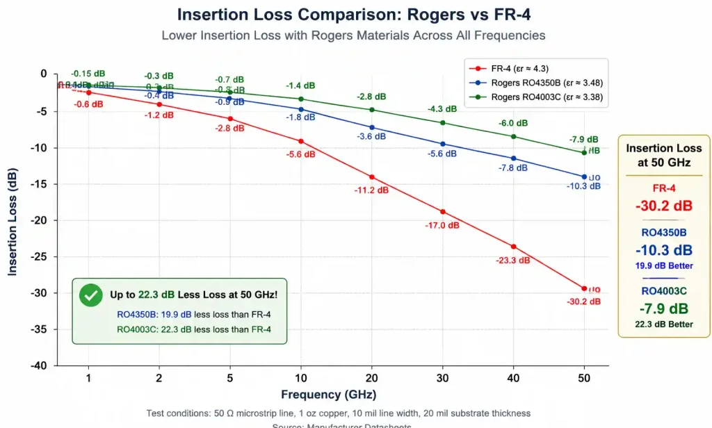
The dissipation factor (Df or tan δ) quantifies how much signal energy converts to heat in the dielectric. FR-4 typically exhibits Df values around 0.02 at microwave frequencies, while Rogers materials like RO4350B deliver Df as low as 0.0037.
This difference compounds over distance. In a 50mm microstrip line at 10 GHz:
- FR-4: Approximately 1.5 dB insertion loss
- RO4350B: Approximately 0.3 dB insertion loss
For power amplifiers, filters, and antenna feed networks, this loss budget difference determines whether your design meets specifications.
Frequency Stability
FR-4’s dielectric properties drift significantly with frequency, making impedance matching difficult across wide bandwidths. Rogers materials maintain stable Dk and Df from MHz through 77 GHz, critical for applications like automotive radar and millimeter-wave 5G.
Thermal Performance
Temperature changes cause FR-4’s dielectric constant to shift unpredictably. Rogers materials offer controlled temperature coefficients, typically between +40 to -40 ppm/°C. For phased array antennas, this prevents beam “squinting” as operating temperature varies.
Rogers Material Series Overview
Rogers Corporation offers several material families, each optimized for different frequency ranges and applications. Selecting the right series narrows your options considerably.
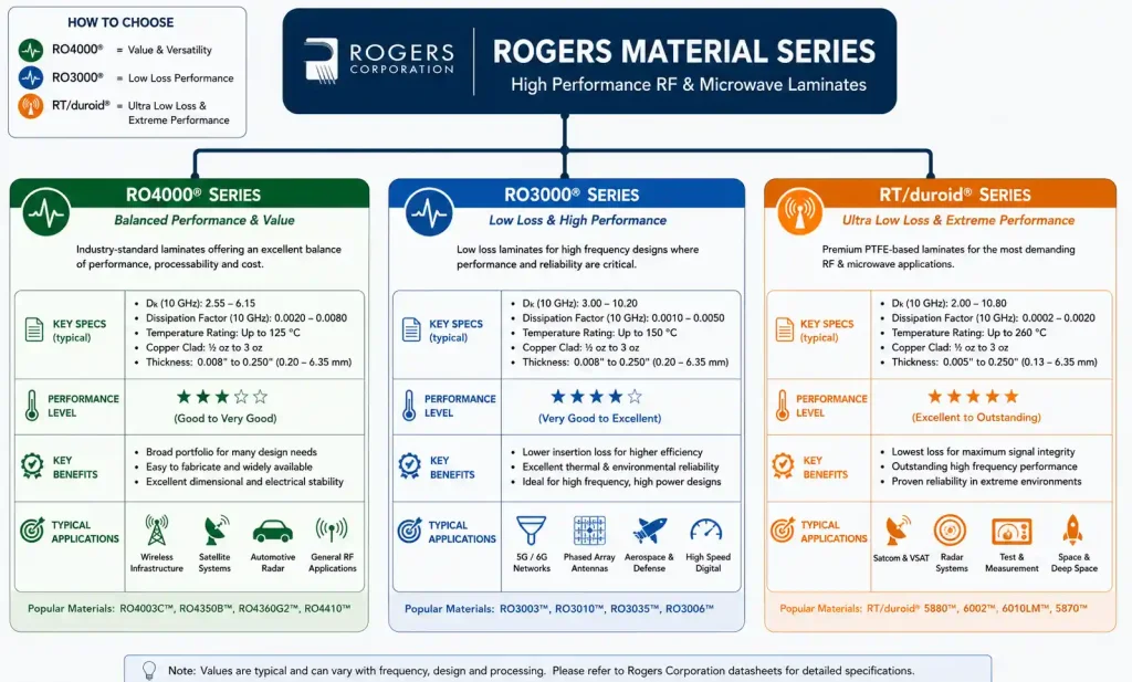
RO4000 Series: The Workhorse
The RO4000 series provides an excellent balance of RF performance and manufacturability. These materials use standard FR-4 fabrication processes, reducing production costs while delivering microwave-grade electrical properties.
Key variants:
- RO4003C (Dk 3.38, Df 0.0027): Cost-effective choice for cellular base stations and automotive applications
- RO4350B (Dk 3.48, Df 0.0037): Widely used for power amplifiers and general RF circuits
- RO4360G2 (Dk 6.15, Df 0.0038): High-Dk option for circuit miniaturization
RO3000 Series: Ceramic-Filled PTFE
These ceramic-filled PTFE composites target commercial microwave applications requiring exceptional dimensional stability and low loss.
Popular options:
- RO3003 (Dk 3.00, Df 0.0013): Ultra-low loss for demanding microwave circuits
- RO3010 (Dk 10.2, Df 0.0035): High-Dk for antenna miniaturization
- RO3035 (Dk 3.50, Df 0.0015): Optimized for 77GHz automotive radar
RT/duroid Series: Premium Performance
The RT/duroid family represents Rogers’ highest-performance materials, used primarily in aerospace, defense, and test equipment.
Notable materials:
- RT/duroid 5880 (Dk 2.20, Df 0.0009): Lowest loss available, ideal for filters and low-noise amplifiers
- RT/duroid 6002 (Dk 2.94, Df 0.0012): Balance of low loss and dimensional stability
Dielectric Constant Matching Strategies
Successful RF PCB design requires matching your substrate’s Dk to your circuit’s specific requirements. This goes beyond simply picking a low-loss material.
Impedance-Driven Selection
Start with your target impedance and trace width constraints. For 50Ω microstrip on 0.5mm substrate:
- Dk 2.20 (5880): Requires ~1.2mm trace width
- Dk 3.38 (RO4003C): Requires ~0.9mm trace width
- Dk 10.2 (RO3010): Requires ~0.3mm trace width
Tighter spaces favor higher Dk materials, but manufacturability limits narrow traces to about 0.1mm in production.
Mixed-Dielectric Stackups
Complex designs often benefit from hybrid stackups combining Rogers materials with FR-4. This approach puts high-frequency signals on Rogers layers while using inexpensive FR-4 for power distribution and low-speed digital signals.
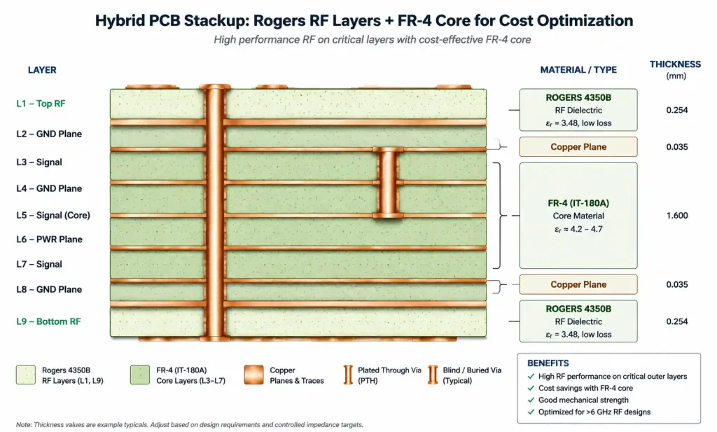
A typical 5G base station PCB might use:
- Top layer: RO4350B for RF front-end
- Inner layers: FR-4 for power and control signals
- Bottom layer: RO4350B for RF output
This hybrid approach optimizes both performance and cost.
Frequency-Dependent Considerations
As frequency increases, Dk tolerance becomes increasingly critical:
- Below 2 GHz: ±5% Dk tolerance usually acceptable
- 2-10 GHz: ±2% Dk tolerance recommended
- Above 10 GHz: ±1% Dk tolerance often necessary
For 77 GHz automotive radar, even 1% Dk variation causes noticeable performance degradation, making materials like RO3035 with ultra-tight tolerances essential.
Key Selection Criteria Beyond Dk
While dielectric constant matching gets most attention, other material properties significantly impact RF PCB success.
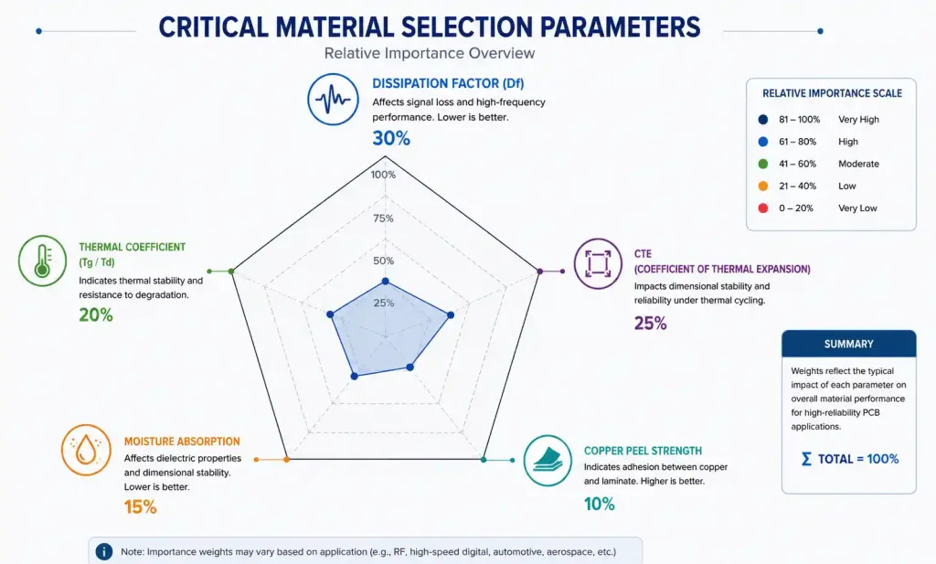
Dissipation Factor (Loss Tangent)
The Df directly determines your signal power budget. For cascaded RF systems, losses accumulate:
- Low-noise amplifiers: Minimize input loss to preserve noise figure
- Power amplifiers: Minimize output loss to maximize delivered power
- Filters: Loss directly degrades insertion loss and Q-factor
Materials with Df below 0.002 (like RO3003) suit the most demanding applications, while Df around 0.004 (like RO4350B) works for many general-purpose designs.
Thermal Coefficient of Dk (TCDk)
TCDk measures how much Dk changes with temperature. For circuits operating across wide temperature ranges, this parameter prevents performance drift:
- ±50 ppm/°C or less: Excellent (RO3003, RO3035)
- ±50 to ±100 ppm/°C: Good (RO4003C, RO4350B)
- Above ±100 ppm/°C: Challenging for precision RF
Automotive and aerospace applications particularly demand low TCDk to maintain performance from -40°C to +125°C.
Copper Peel Strength
Adequate copper adhesion prevents delamination during thermal cycling and mechanical stress. Rogers materials typically achieve >1.0 N/mm peel strength, but this varies by series and copper treatment.
Coefficient of Thermal Expansion (CTE)
CTE matching between substrate, copper, and components prevents mechanical failures. Rogers materials offer controlled CTE in both X-Y (12-17 ppm/°C) and Z-axis (24-70 ppm/°C) directions.
Moisture Absorption
Water absorption changes dielectric properties and causes dimensional instability. Rogers materials typically absorb <0.1% moisture, far superior to FR-4’s ~0.4%.
Common Rogers Materials Comparison
Here’s a practical comparison of frequently specified Rogers materials to guide your selection:
| Material | Dk @ 10GHz | Df @ 10GHz | TCDk (ppm/°C) | Best Applications |
|---|---|---|---|---|
| RO4003C | 3.38 | 0.0027 | +40 | Base stations, general RF |
| RO4350B | 3.48 | 0.0037 | +50 | Power amps, mixed-signal |
| RO3003 | 3.00 | 0.0013 | +13 | Low-loss microwave circuits |
| RO3035 | 3.50 | 0.0015 | +40 | 77GHz radar, millimeter-wave |
| RO3010 | 10.2 | 0.0035 | -18 | Antenna miniaturization |
| RT5880 | 2.20 | 0.0009 | -4 | Filters, precision circuits |
| RO4360G2 | 6.15 | 0.0038 | +40 | Compact designs, couplers |
RO4003C vs RO4350B
These two materials compete in many applications:
Choose RO4003C when:
- Cost sensitivity is important
- Operating below 10 GHz
- Standard FR-4 process compatibility needed
Choose RO4350B when:
- Higher operating temperatures expected
- Better thermal reliability required
- Lead-free processing needed
When to Select High-Dk Materials
High dielectric constant materials (Dk > 6) enable significant miniaturization:
- Patch antennas reduce 40-50% in size
- Branch-line couplers shrink proportionally
- Filters achieve tighter coupling
However, higher Dk also means:
- Tighter impedance tolerances required
- More challenging fabrication
- Increased dispersion in wideband circuits
Application-Specific Material Selection
Different RF applications have distinct material requirements. Here’s how to match Rogers materials to your specific use case.
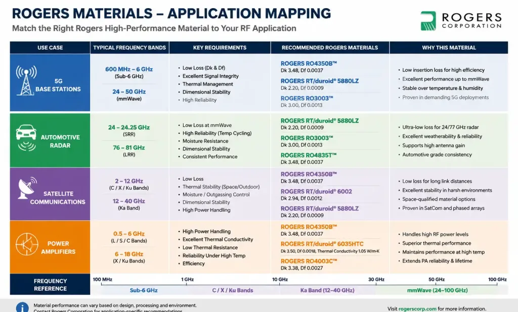
5G Infrastructure (Sub-6GHz and mmWave)
5G base stations operate across massive frequency ranges, from 600 MHz to 39 GHz. Material selection depends on the band:
Sub-6GHz: RO4350B or RO4003C provide adequate performance at reasonable cost. The wider wavelengths tolerate standard tolerances.
mmWave (24-39GHz): RO3003 or RO3035 deliver the tight Dk tolerances and low loss essential at these frequencies. Even small variations create phase errors in beamforming networks.
Automotive Radar (77GHz)
Automotive radar demands exceptional Dk stability across -40°C to +125°C. RO3035 specifically targets this application with its low TCDk and stable Df.
The tight temperature coefficient prevents beam squinting, where antenna radiation patterns shift with temperature—unacceptable in safety-critical ADAS systems.
Satellite Communication
Satellite terminals balance size, weight, and power constraints while operating from GHz to Ka-band frequencies. Material choices include:
- Ku-band (12-18GHz): RO4350B or RO3003
- Ka-band (26-40GHz): RO3003 or RT5880
- Phased arrays: High-Dk materials like RO3010 or RO4360G2 for compact element spacing
Power Amplifiers
PA designs prioritize thermal management alongside RF performance. RO4350B’s higher thermal conductivity (0.69 W/m·K) helps dissipate heat compared to RO4003C (0.64 W/m·K), though both exceed FR-4 significantly.
For high-power applications above 10W, consider enhanced thermal management through embedded copper coins or thicker copper weights.
Low-Noise Amplifiers (LNAs)
LNAs demand minimal input loss to preserve noise figure. RT5880’s ultra-low Df (0.0009) minimizes loss ahead of the active device, preserving system sensitivity.
Even 0.2 dB of substrate loss before the LNA directly degrades cascade noise figure—critical for receiver front-ends.
Cost vs Performance Trade-offs
Rogers materials command premium pricing compared to FR-4. Strategic material selection optimizes your budget without sacrificing essential RF performance.
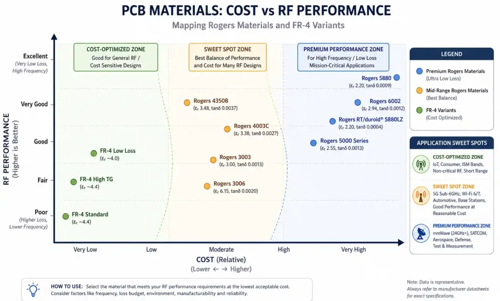
When FR-4 Actually Works
Don’t default to Rogers for every high-frequency design. Modern low-loss FR-4 variants (like Megtron-6 or I-Tera MT40) handle frequencies up to 5-6 GHz adequately for:
- Impedance-controlled digital signals (PCIe, USB, HDMI)
- Lower-frequency RF (below 2 GHz)
- Non-critical RF sections
Reserve Rogers materials for circuit sections where loss and Dk stability truly matter.
Hybrid Stackup Economics
A typical 8-layer PCB for 5G small cells might use:
- Layers 1, 8: RO4350B (RF front-end, antenna feeds)
- Layers 2-7: FR-4 (power, control, digital interfaces)
This approach adds roughly 30-50% to the base FR-4 cost while delivering 90% of an all-Rogers design’s RF performance.
Volume Considerations
Rogers material pricing becomes more competitive at higher volumes:
- Prototype (1-10 boards): 3-5× FR-4 cost
- Small production (100-500): 2-3× FR-4 cost
- High volume (>10,000): 1.5-2× FR-4 cost
Factor these economics into your product planning and material selection.
Hidden Cost Factors
Beyond material pricing, consider:
- Yield: Rogers materials’ tighter tolerances improve manufacturing yield for precision RF circuits
- Rework: Reduced RF failures decrease costly board iterations
- Testing: Consistent Dk reduces impedance tuning time
These factors often justify the material premium in production environments.
Design Guidelines for Rogers PCBs
Successful Rogers PCB designs require attention to fabrication specifics that differ from standard FR-4 processes.
Stackup Design Best Practices
Collaborate with your PCB fabricator early on stackup definition:
Dielectric thickness: Rogers materials come in standard thicknesses (0.127mm, 0.254mm, 0.508mm, etc.). Design impedances around available thicknesses rather than requiring custom builds.
Copper weights: Standard options are 0.5oz (17μm) and 1oz (35μm). Heavier copper increases cost and fabrication difficulty. For microstrip designs, thinner copper enables tighter coupling and narrower gaps.
Layer registration: Maintain at least 0.15mm clearance for critical RF features. Tighter tolerances require enhanced registration processes that increase cost.
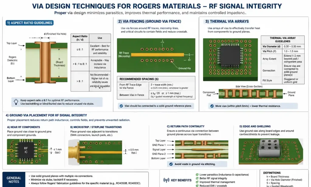
Via Design Considerations
Rogers materials drill similarly to FR-4 but require specific attention:
- Aspect ratio: Limit to 8:1 for reliable plating (e.g., 0.2mm hole in 1.6mm board)
- Via fencing: Use ground via fences spaced <λ/20 around RF traces to prevent coupling
- Thermal vias: For power amplifiers, use via arrays under heat-generating components
Fabrication Process Compatibility
The RO4000 series uses standard FR-4 processes, simplifying fabrication. PTFE-based materials (RO3000, RT/duroid) require specialized handling:
- Different drilling parameters to prevent fiber pullout
- Plasma or chemical treatment for copper adhesion
- Modified lamination cycles
Discuss these requirements with your fabricator before committing to PTFE-based designs.
Assembly Considerations
Rogers materials tolerate standard lead-free reflow profiles (260°C peak). However:
- Limit reflow cycles to 3-4 to prevent degradation
- Use lower preheat rates for thick boards to prevent delamination
- Consider lower-temperature solders (like SAC305) for rework
Conclusion
Selecting Rogers high-frequency PCB materials requires balancing dielectric constant requirements, loss performance, thermal stability, and cost constraints. Start by defining your frequency range, impedance targets, and environmental conditions, then narrow material choices based on these priorities.
For general-purpose RF designs below 10 GHz, RO4350B offers excellent performance at moderate cost. Push toward RO3003 or RO3035 for demanding applications above 10 GHz or harsh environments. Reserve RT/duroid 5880 for applications where ultimate performance justifies the premium.
Mixed-dielectric stackups provide cost-effective solutions for complex systems, placing Rogers materials only where RF performance demands them. Work closely with your PCB fabricator early in the design cycle to ensure your chosen materials align with their capabilities and your budget constraints.
By understanding how dielectric constant matching, loss tangent, and thermal stability interact with your specific application requirements, you can confidently select Rogers materials that optimize both technical performance and project economics.