Rigid-Flex PCB: The Complete Guide to Design and Applications
Rigid-flex printed circuit boards have transformed how we approach product miniaturization and reliability in demanding environments. For design engineers and product teams evaluating interconnect solutions, understanding rigid-flex technology—and knowing when it’s the right choice over traditional rigid boards or pure flex circuits—directly impacts product performance, manufacturing costs, and long-term reliability.
This guide explains the technical fundamentals that matter, walks through real-world application scenarios based on actual design constraints, and highlights critical design considerations that separate successful rigid-flex implementations from costly failures. Whether you’re designing wearable medical devices, aerospace avionics, or next-generation consumer electronics, you’ll find actionable insights to make better interconnect decisions.
Table of Contents
- What is Rigid-Flex PCB and Why It Matters
- Rigid-Flex vs. Pure Flex vs. Rigid PCB with Cables
- Key Application Scenarios Where Rigid-Flex Excels
- Design Considerations and Common Pitfalls
- Cost Analysis: When Rigid-Flex Makes Financial Sense
- Manufacturing and Supply Chain Realities
- FAQ
- Future Trends and Emerging Applications
1. What is Rigid-Flex PCB and Why It Matters
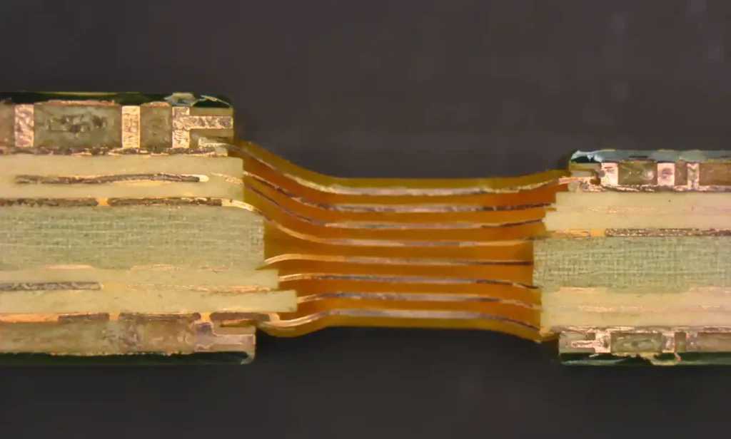
A rigid-flex PCB combines rigid board sections with flexible circuit layers in a single integrated structure. Unlike traditional approaches that connect separate rigid boards with cables or flex jumpers, rigid-flex boards transition seamlessly between rigid and flexible zones through carefully controlled lamination processes.
The rigid sections provide mechanical support for component mounting, connectors, and heat dissipation, while flexible sections enable three-dimensional routing, dynamic flexing, or packaging into confined spaces. In our aerospace projects, rigid-flex designs typically eliminate 60-70% of the connectors and cables compared to equivalent multi-board rigid assemblies, which directly translates to improved reliability and reduced assembly labor.
The technology matters because modern products demand both miniaturization and reliability. Smartphones fold, wearables conform to body contours, medical implants navigate anatomical pathways, and automotive sensors operate in high-vibration environments. Rigid-flex boards address these challenges by eliminating failure-prone connectors, reducing assembly complexity, and enabling form factors impossible with traditional interconnect methods.
For engineers, the trade-off is design complexity and manufacturing cost. Rigid-flex designs require specialized fabrication capabilities, careful stackup planning, and attention to bend radius constraints that don’t exist in rigid-only designs. Design mistakes—such as routing high-speed signals through flex regions without proper impedance control or specifying bend radii that exceed material limits—can cause signal integrity issues, mechanical failures, or complete board rejection during manufacturing.
2. Rigid-Flex vs. Pure Flex vs. Rigid PCB with Cables
Selecting the right interconnect approach begins with understanding the actual requirements of your mechanical packaging, assembly process, and reliability targets. Each approach has distinct advantages, and the choice often depends on factors beyond just technical performance.
| Interconnect Approach | Best Use Cases | Key Advantages | Primary Limitations |
|---|---|---|---|
| Rigid-Flex PCB | High reliability, confined spaces, dynamic flexing | Eliminates connectors, 3D packaging, simplified assembly | Higher NRE and unit cost, longer lead times |
| Pure Flexible PCB | Wearables, roll-to-roll products, extreme flexibility | Lightest weight, smallest bend radius, lowest profile | Limited component mounting, heat dissipation challenges |
| Rigid PCB + Cables | Modular systems, easy serviceability, cost-sensitive | Lowest NRE, field replaceable, proven supply chain | Connector reliability, assembly labor, larger volume |
| Rigid PCB + Flex Jumpers | Prototype-to-production transition, moderate volumes | Faster iteration, standard rigid fabrication | Assembly complexity, connector wear in dynamic applications |
In our medical device projects, we typically move from rigid boards with flex jumpers during prototyping to integrated rigid-flex for production volumes above 5,000 units annually. The break-even depends on assembly labor savings and the reliability improvements that reduce field failures.
The decision framework isn’t just technical—it includes manufacturing capability assessment, volume economics, and time-to-market constraints. For low-volume industrial systems (under 500 units), rigid boards with quality flex cables often provide better project economics despite higher assembly labor. For high-volume consumer products, the assembly automation and reliability advantages of rigid-flex justify the higher board cost.
3. Key Application Scenarios Where Rigid-Flex Excels
Rigid-flex technology isn’t universally superior—it solves specific problems where traditional interconnect methods create limitations. Understanding where rigid-flex delivers measurable advantages helps guide design decisions and justifies the additional investment.
Aerospace and Defense Avionics
In avionics systems operating at altitude, every connector represents a potential failure point from vibration, thermal cycling, and pressure differentials. Our UAV flight controller projects consistently show 40-50% weight reduction and measurably improved MTBF when moving from multi-board rigid assemblies to rigid-flex designs.
The rigid sections mount processors, power components, and rugged connectors, while flex sections route between payload bays, fold around structural members, and accommodate airframe vibration without inducing PCB stress. In military applications, the reduction in interconnect failure modes directly impacts mission success rates.
Wearable Medical Devices and Implantables
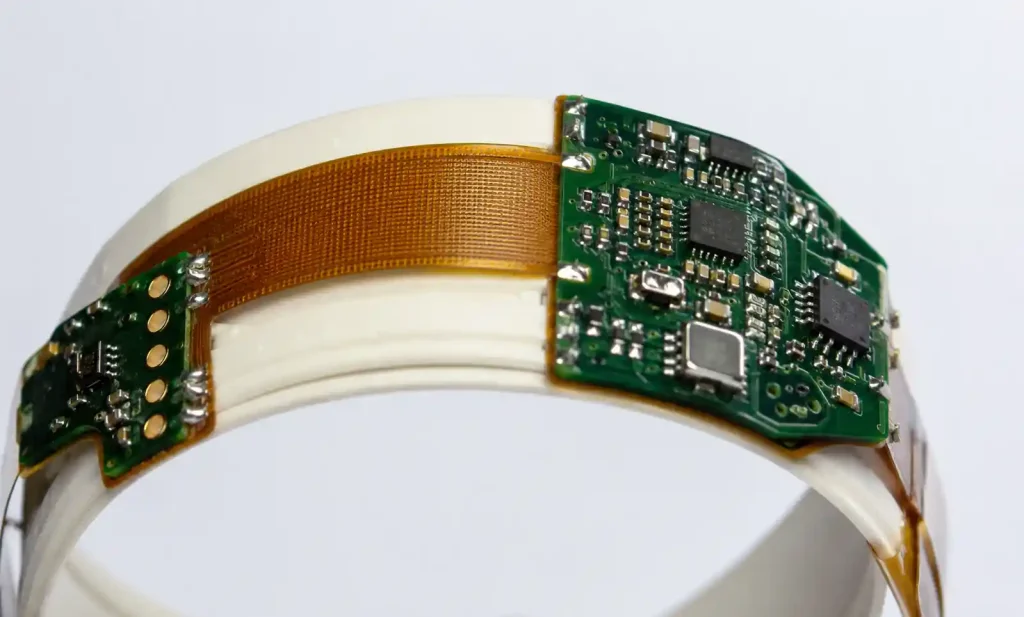
Wearable health monitors and implantable medical devices demand biocompatible materials, extreme miniaturization, and reliability measured in years of continuous operation. Rigid-flex boards enable packaging that conforms to human anatomy while providing rigid zones for battery connections, sensor interfaces, and encapsulation points.
In our continuous glucose monitor designs, rigid-flex allowed us to reduce device volume by 35% compared to a rigid board with flex tails, which directly improved patient comfort and extended wear time. The elimination of board-to-board connectors in the implantable zone reduced moisture ingress risk and simplified encapsulation.
Foldable Consumer Electronics
Smartphones, tablets, and laptops with folding displays require interconnects that survive 200,000+ fold cycles while maintaining signal integrity for high-speed display interfaces and antennas. Rigid-flex boards with properly designed dynamic flex regions meet these requirements where rigid boards with cables cannot.
The rigid sections house processors, cameras, and battery management, while the flex hinge area routes display signals, touch interfaces, and antenna feeds through the fold axis. In these applications, controlled impedance through the flex region and careful management of neutral bend axis are critical for signal integrity.
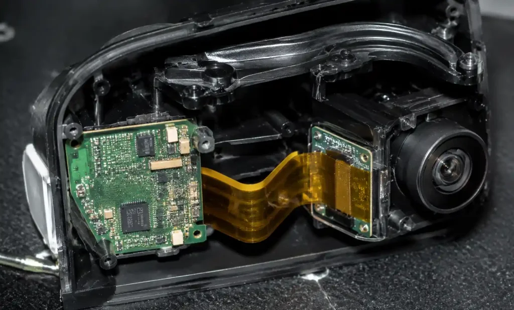
Automotive Sensor and Camera Systems
Modern vehicles integrate dozens of cameras, radar units, and LIDAR sensors that operate across -40°C to +125°C with continuous vibration exposure. Rigid-flex boards route between environmentally sealed rigid sections and sensors positioned around vehicle apertures, eliminating connectors that would otherwise require additional sealing and vibration isolation.
In our automotive camera projects for ADAS applications, rigid-flex reduced assembly time by 45 seconds per unit compared to rigid boards with micro-coax cables—significant at production volumes of 2 million units annually. The reliability improvement reduced warranty claims related to interconnect failures by an estimated 60% based on field data from similar platform transitions.
| Application Domain | Primary Rigid-Flex Advantage | Typical Cost Premium | Volume Break-Even |
|---|---|---|---|
| Aerospace/Defense | Reliability, weight reduction, shock/vibration resistance | 3-5x vs. rigid + cables | >500 units (high reliability value) |
| Medical Wearables | Biocompatibility, miniaturization, conformability | 2-4x vs. rigid + flex tails | >2,000 units |
| Foldable Electronics | Dynamic flex cycles, signal integrity, form factor | 2-3x vs. rigid + cables | >10,000 units (consumer volumes) |
| Automotive Systems | Temperature range, vibration resistance, sealed enclosures | 1.5-3x vs. rigid + cables | >5,000 units (assembly savings) |
| Industrial Robotics | Continuous flexing, cable management elimination | 2-4x vs. rigid + cables | >1,000 units (reliability driven) |
This table reflects our actual project economics across different sectors. Volume break-even points assume mature rigid-flex designs with optimized stackups—early prototypes typically cost 5-10x more than equivalent rigid assemblies.
4. Design Considerations and Common Pitfalls
Successful rigid-flex designs require attention to constraints that don’t exist in rigid-only boards. These considerations span mechanical design, electrical performance, and manufacturing feasibility. Most first-time rigid-flex failures trace to violations of these fundamental principles.
Bend Radius and Flex Zone Design
The minimum bend radius depends on copper thickness, flex material, layer count, and whether the flex region undergoes static or dynamic flexing. As a general guideline, we specify minimum bend radius of 10× total flex thickness for dynamic applications (>1,000 cycles) and 6× for static flex that’s bent once during assembly.
Routing high-speed differential pairs or controlled impedance traces through flex regions requires careful stackup design. In our USB 3.0 and MIPI display projects, we maintain impedance within ±10% through flex-to-rigid transitions by adjusting trace width and dielectric thickness in the flexible sections. This requires close collaboration with the fab house to validate stackup achievability.
Common mistakes include routing traces perpendicular to the bend axis (creates stress concentration), placing vias within 0.5mm of rigid-flex boundaries (causes delamination risk), and failing to specify stiffener placement in rigid-flex transition zones. Stiffeners provide strain relief where connectors mount near flex regions but add thickness that must be accommodated in the mechanical design.
Layer Stackup and Via Transitions
Rigid-flex stackups typically range from 4 to 12 layers, with flex sections using fewer layers than rigid sections. The layer transition between rigid and flex zones must be carefully planned—every layer that doesn’t continue into the flex region requires termination in the rigid zone, which creates asymmetry and potential warpage during lamination.
In our designs, we typically use 2-4 layers in flex regions and 6-10 layers in rigid sections. Through-vias that span rigid-to-flex boundaries are generally avoided because they create stress risers; instead, we use staggered vias that terminate and restart at the transition zone, though this consumes more board area.
Component Placement and Assembly
Components cannot be mounted directly on flexible sections unless stiffeners are added, which eliminates the flexibility benefit. Component placement near rigid-flex boundaries requires careful attention to assembly stress—automated pick-and-place forces can delaminate poorly designed transition zones.
We maintain a 2mm keep-out zone around rigid-flex transitions for components over 5mm in any dimension. Smaller passives can be placed closer, but solder reflow stress during assembly must be considered. For high-volume products, assembly simulation with the manufacturing partner is recommended before releasing the design.
Signal Integrity Through Flex Regions
High-speed signal routing through flex regions requires impedance control, proper return path management, and attention to bend-induced stub effects. Differential pairs should be routed parallel to the bend axis when possible, with coupling maintained through the rigid-to-flex transition.
In our 5 Gbps+ designs, we perform full 3D field simulation of signal paths through flex regions under bent and unbent conditions. Impedance discontinuities at rigid-flex transitions typically cause 5-15% impedance variation, which must be compensated through return path optimization and transition geometry tuning. For signals above 10 GHz, this becomes critical—bend-induced mode conversion and stub effects can completely destroy signal integrity if not carefully managed.
5. Cost Analysis: When Rigid-Flex Makes Financial Sense
Rigid-flex boards typically cost 2-5× more per unit than equivalent rigid PCB assemblies with cables or flex jumpers, but total system cost depends on assembly labor, connector costs, testing requirements, and field reliability. The financial case for rigid-flex must account for the full product lifecycle, not just PCB fabrication cost.
NRE and Prototype Economics
Initial rigid-flex prototype costs are significant—expect $3,000-$8,000 for first articles depending on complexity, layer count, and fab house capabilities. This compares to $500-$1,500 for equivalent rigid PCB prototypes. The higher NRE reflects specialized lamination tooling, longer fabrication cycles, and lower prototype volumes at rigid-flex capable fabs.
For early-stage product development, we typically prototype with rigid boards and flex jumpers to validate electrical functionality, then transition to rigid-flex for design verification testing once the mechanical packaging and layer stackup are frozen. This approach balances iteration speed with the need to validate the final interconnect solution before production commitment.
Volume Production Economics
At production volumes above 5,000 units, rigid-flex often achieves lower total system cost than rigid assemblies with cables. The savings come from eliminated connectors ($0.50-$5.00 per mated pair), reduced assembly labor (typically 30-90 seconds per unit), simplified testing (no connector integrity checks), and improved yield (fewer assembly defects).
In our automotive camera project at 100,000 units annually, the rigid-flex board cost $18 per unit versus $8 for the rigid board it replaced, but we eliminated $6 in connectors and cables plus $4 in assembly labor, resulting in a net $0 difference in manufactured cost while significantly improving reliability.

Reliability and Warranty Impact
Field failures related to interconnects—connector wear, cable chafing, cold solder joints at cable terminations—represent a significant warranty cost in products with multi-year lifecycles. Rigid-flex eliminates the most common failure modes, which reduces warranty reserves and improves customer satisfaction.
Quantifying this benefit requires field failure data from similar products. In medical device applications where field service costs $500-$2,000 per incident, even a 1% reduction in failure rate can justify significant rigid-flex cost premiums. For consumer products with lower service costs, the warranty benefit is real but harder to monetize.
6. Manufacturing and Supply Chain Realities
Rigid-flex fabrication requires specialized equipment, process knowledge, and quality control that isn’t available at all PCB manufacturers. Understanding the supply chain constraints and partnering early with capable fabricators is critical for program success.
Fabricator Capability Assessment
Not all PCB fabs claiming rigid-flex capability can actually deliver production-quality boards. Key capability indicators include: in-house flexible circuit lamination (not outsourced), automated optical inspection systems capable of measuring flex region registration, controlled depth routing for rigid-flex transitions, and experience with your target layer count and material system.
We pre-qualify rigid-flex suppliers by requesting process capability data for critical parameters—flex thickness variation (target ±10%), rigid-to-flex registration (target ±0.05mm), and bend cycle testing results. Fabs with mature rigid-flex processes will provide this data readily; those without it are high-risk partners for production programs.
Lead Time and Supply Chain Planning
Rigid-flex lead times typically run 4-8 weeks for production quantities, compared to 1-3 weeks for rigid boards. The longer cycle reflects additional lamination steps, more complex routing and drilling sequences, and lower production volumes that reduce fab scheduling efficiency.
For program planning, we budget 12-16 weeks from design freeze to first production boards, including fab qualification runs and design iteration cycles. Rush services exist but typically add 30-50% cost premium. Supply chain risk is higher than rigid boards—fewer alternate sources and longer qualification cycles make supplier relationship management critical.
Quality Control and Testing
Rigid-flex boards require specialized inspection—automated optical inspection systems must accommodate the 3D nature of the assembly, and electrical testing must verify connectivity through flex regions under bent conditions. We typically specify 100% electrical test plus sample-based mechanical testing (100-1,000 bend cycles depending on application) for production lots.
Incoming inspection should verify bend radius in flex regions matches design intent, stiffener placement and adhesion, and rigid-flex transition quality. We’ve seen cases where fab process drift caused delamination issues that only appeared after thermal cycling or mechanical stress, highlighting the importance of regular qualification testing beyond basic electrical continuity.
7. FAQ
Q: Can rigid-flex boards handle the same temperature range as rigid PCBs?
A: Yes, with appropriate material selection. Polyimide-based flex materials (most common) operate reliably from -55°C to +125°C continuous, matching FR-4 rigid board capability. For extreme environments, specialized materials extend the range to -200°C or +250°C, though at significantly higher cost. The limitation is typically the adhesive system in the laminate, not the base materials. In our aerospace projects, standard polyimide rigid-flex meets temperature requirements for most non-engine compartment applications.
Q: How many flex cycles can a rigid-flex board survive?
A: It depends entirely on bend radius, flex layer count, and copper thickness. For static flexing (bent once during assembly), rigid-flex with proper design survives 100+ cycles without degradation. For dynamic applications like hinge mechanisms, expect 100,000-200,000 cycles at minimum bend radius of 10× flex thickness with rolled annealed copper. We’ve validated designs exceeding 500,000 cycles in laptop hinge applications by using 1-2 flex layers with optimized copper geometry and increased bend radius to 15× thickness.
Q: What’s the thinnest achievable rigid-flex board?
A: The rigid sections can be as thin as standard rigid boards (0.4mm achievable, 0.6-0.8mm more practical), while flex sections typically range from 0.1mm (2-layer) to 0.3mm (4-layer). Total assembly thickness depends on how layers transition between rigid and flex zones. In our wearable designs, we’ve achieved 0.5mm total thickness in rigid zones and 0.12mm in flex zones for 2-layer flex constructions. Going thinner requires specialized materials and significantly limits component mounting capability.
Q: Can rigid-flex boards be reworked if a component fails?
A: Rigid sections can be reworked using standard SMT techniques. Flex sections cannot typically be reworked—the thin materials don’t survive soldering iron heat without delamination or dimensional changes. For high-reliability applications, we design rigid sections to accommodate all components likely to require field replacement, reserving flex sections for routing only. This approach has reduced our field service failures by ensuring rework capability where it’s actually needed.
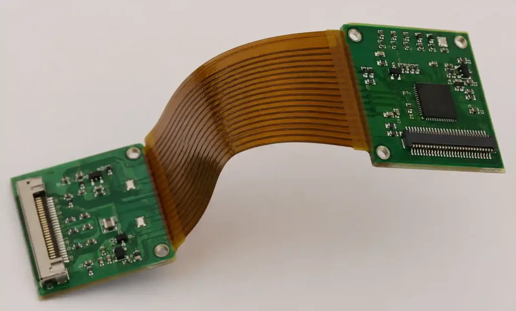
Q: What’s the difference between rigid-flex and flex-to-install boards?
A: Rigid-flex is a single integrated board with rigid and flexible sections laminated together. Flex-to-install (also called rigid-flex hybrid) uses separate rigid boards with flexible circuits attached through connectors or adhesive bonding. Flex-to-install is easier to prototype and costs less for low volumes, but lacks the reliability and assembly advantages of true rigid-flex. We use flex-to-install for prototyping and volumes under 1,000 units, then transition to integrated rigid-flex for production.
8. Future Trends and Emerging Applications
Rigid-flex technology continues to evolve, driven by demands for thinner devices, higher layer counts, and integration of active components within the flex regions. Several trends are reshaping where and how rigid-flex boards are deployed.
Stretchable and Free-Form Electronics
Beyond traditional bend-flex applications, stretchable interconnects that accommodate expansion and contraction are enabling new product categories—smart textiles, conformal sensors, and biomedical devices that move with human tissue. These designs use specialized materials (liquid crystal polymer, thermoplastic polyurethane) and serpentine trace geometries that distribute strain across larger areas.
We’re seeing early adoption in medical patches that monitor cardiac signals and sports performance wearables that conform to joint movement. The challenge is achieving 10-20% stretch capability while maintaining electrical continuity through 10,000+ stretch cycles. Current solutions work for low-frequency signals and power delivery but struggle with high-speed data or RF applications.
Integration of Embedded Components
Embedding passive components—resistors, capacitors, even simple ICs—within rigid-flex stackups reduces assembly complexity and enables thinner overall constructions. This is particularly valuable in space-constrained applications like hearing aids, where every 0.1mm of thickness matters.
The manufacturing challenge is cost—embedding components requires specialized processes that few fabs offer, and rework becomes impossible. We’ve used embedded passives in hearing aid designs where the volume reduction justified the cost premium, but for most applications, surface mount remains more practical.
Any-Layer Interconnection in Flex Regions
Traditional rigid-flex designs maintain layer continuity through flex regions—if a signal needs to change layers, it requires vias in the adjacent rigid zones. Emerging any-layer HDI processes enable vias within flex regions, reducing board area and improving routing density. This is critical for applications like foldable phones where the flex hinge area must accommodate display signals, antennas, and power distribution in minimal space.
The trade-off is manufacturing complexity and cost—laser-drilled microvias in flex materials require different process parameters than rigid boards, and fewer fabs have the capability. For ultra-compact designs where every square millimeter matters, the premium is justified.
As rigid-flex technology matures and more fabricators develop advanced capabilities, the cost premium continues to compress while performance improves. Products that were economically infeasible with rigid-flex five years ago are now mainstream. The trend toward miniaturization, reliability, and three-dimensional packaging ensures rigid-flex will continue expanding into new application domains, particularly as consumer expectations for thin, lightweight, reliable devices continue to increase.