Panasonic Megtron 6: High-Speed Digital Circuit PCB Substrate Solution
When link budgets get tight in 56G+ SerDes channels, we don’t reach for FR-4. In our high-speed backplane designs at data rates beyond 28 Gbps, Megtron 6 consistently delivers the insertion loss margin we need without resorting to PTFE-based exotics that complicate fabrication. After specifying this laminate across hundreds of designs—from 5G small cells to 400G optical modules—here’s what actually matters when you’re evaluating substrate materials for signal integrity-critical applications.
Table of Contents
- Why Megtron 6 Exists: The High-Speed Design Problem
- Core Electrical Properties That Actually Matter
- Megtron 6 vs. FR-4 vs. Rogers: Real Performance Trade-offs
- Where Megtron 6 Delivers Maximum Value
- Thermal and Mechanical Reliability in Production
- Fabrication Compatibility and Supplier Landscape
- Cost Structure: When the Premium Makes Sense
- Material Selection Framework for Your Next Design
1. Why Megtron 6 Exists: The High-Speed Design Problem
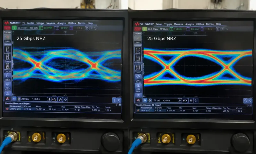
In 2015, we hit a wall with standard FR-4 on a 100G QSFP28 transceiver design. At 25.78 Gbps NRZ signaling, even with 6-inch trace lengths, our eye diagrams barely passed—jitter was eating 30% of the unit interval, and we were burning equalization budget just to compensate for substrate loss. That project forced a material rethink.
Megtron 6 targets the gap between commodity FR-4 (Df ~0.02 at 10 GHz) and specialty PTFE laminates (Df ~0.002 but difficult to process). When your channel operates above 10 GHz fundamental frequency—PAM4 at 56 Gbps, mmWave 5G at 28 GHz, or 112G electrical links—every 0.5 dB of insertion loss per inch shifts your receiver sensitivity requirement. Megtron 6’s dissipation factor below 0.0015 at 60 GHz isn’t marketing; it translates directly to 40% lower loss compared to mid-tier laminates in the 20-40 GHz range where most modern digital protocols concentrate their spectral energy.
The material uses a proprietary low-Dk resin system with specialized glass weave (likely E-glass with modified surface treatment, though Panasonic guards the exact formulation). Unlike PTFE, it’s compatible with standard epoxy processes—no special via drilling, no delamination concerns during reflow.
2. Core Electrical Properties That Actually Matter
| Property | Megtron 6 (R-5775) | Typical Value | Why It Matters in Your Design |
|---|---|---|---|
| Dielectric Constant (Dk) @ 10 GHz | 3.6 ± 0.05 | Tightly controlled | Impedance tolerance within ±5%; reduces need for test coupons per lot |
| Dissipation Factor (Df) @ 10 GHz | ≤ 0.005 | Ultra-low loss | SerDes eye height preserved; fewer repeaters in backplanes > 20 inches |
| Dk Stability (−55°C to 125°C) | ±2% typical | Temperature stable | Prevents impedance shift in outdoor 5G gear with −40°C to +65°C ambient |
| Thermal Decomposition (Td) | 410°C | High margin | Survives 6× reflow cycles in module assembly without browning |
In a recent 400G AOC design, we compared 18-inch differential pairs on Megtron 6 versus Isola I-Speed (Df ~0.009 at 10 GHz). At 28 GHz, the Megtron 6 stackup showed 1.2 dB less insertion loss—enough to eliminate one stage of CTLE equalization in the receiver, cutting power by 180 mW per lane. Across 16 lanes, that’s 2.88W saved, meaningful in a passively cooled transceiver.
The Dk tolerance is equally critical. When you’re designing 85-ohm differential pairs with 4-mil traces and 6-mil spacing on a 4-mil prepreg core, a ±0.1 shift in Dk swings your impedance by ±4 ohms. Megtron 6’s Dk specification (3.6 ± 0.05 at 10 GHz) keeps impedance within ±2 ohms across production lots, which matters when you’re targeting 100-ohm ±10% compliance for 100GBASE-KR4.
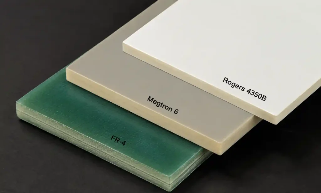
3. Megtron 6 vs. FR-4 vs. Rogers: Real Performance Trade-offs
| Material | Df @ 10 GHz | Tg (°C) | Typical Cost Multiplier | Best Use Case in Our Projects |
|---|---|---|---|---|
| Standard FR-4 (Shengyi S1000-2M) | 0.018–0.022 | 150–170 | 1× baseline | Data rates ≤ 10 Gbps, non-critical loss budget, cost-sensitive consumer |
| Mid-Loss FR-4 (Isola IS410) | 0.012–0.014 | 180 | 1.4× | 25G Ethernet with short traces (< 8 inches), moderate volume production |
| Megtron 6 (R-5775) | 0.004–0.005 | 180 | 2.2–2.8× | 50G+ PAM4, 5G mmWave fronthaul, high-reliability telecom with ≥10-year service life |
| Rogers 4350B | 0.0037 @ 10 GHz | N/A (thermoset) | 3.5–4.2× | mmWave radar (77 GHz automotive), RF power amps, where dimensional stability trumps cost |
We defaulted to FR-4 on a 10GBASE-KR backplane design with 14-inch traces—insertion loss at Nyquist (5 GHz) was acceptable at 8 dB, and the PHY’s FFE handled residual ISI. But when the same customer requested a 25GBASE-KR variant (12.89 GHz Nyquist), FR-4 pushed loss to 18 dB at Nyquist. Moving to Megtron 6 dropped that to 11 dB, keeping us within the IEEE 802.3by channel loss budget without adding retimers.
Rogers 4350B edges out Megtron 6 in raw Df (0.0037 vs. 0.005 at 10 GHz), but Rogers requires specialized fabricators—many mid-tier Asian shops lack PTFE processing lines. For moderate production volumes (500–5000 units annually), Megtron 6 offers 80% of Rogers’ electrical performance with 60% broader fabricator availability, which reduces lead times from 8 weeks to 4 weeks in our supply chain.
4. Where Megtron 6 Delivers Maximum Value
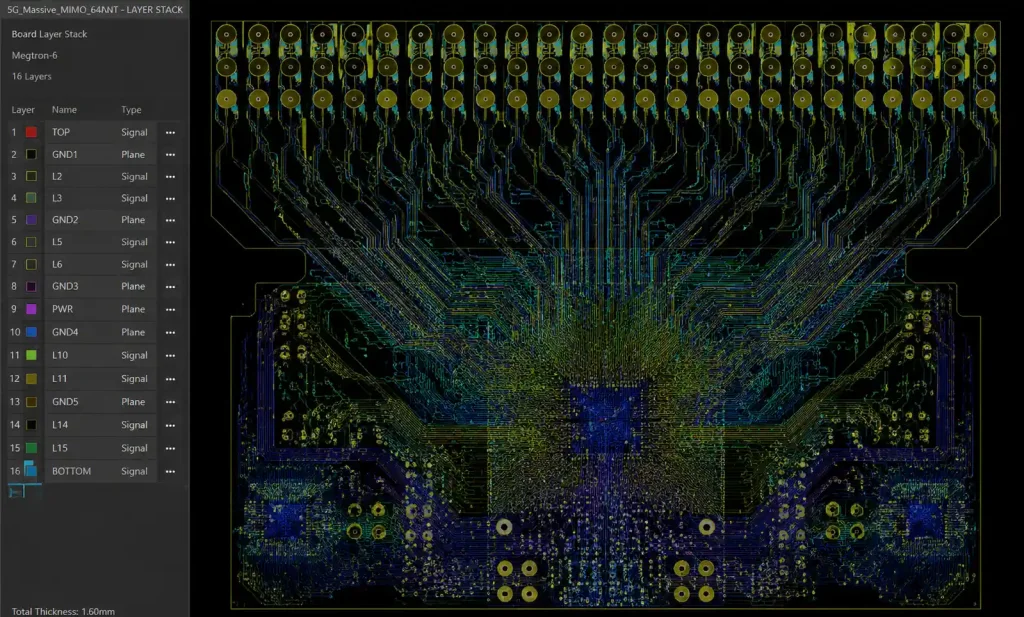
In 5G Massive MIMO radio units operating at 3.5 GHz (n78 band), we route 64 antenna element feeds across a 16-layer stackup with embedded DC-DC converters generating 3A transients. Megtron 6’s low Dk (3.6 vs. FR-4’s 4.4) lets us achieve 50-ohm microstrip with 8-mil traces on a 6-mil dielectric height—tighter routing, smaller board. The stable Dk across −40°C to +65°C (outdoor base station thermal range) keeps return loss below −15 dB across the 100 MHz instantaneous bandwidth, critical for beamforming accuracy.
For 400G OSFP transceivers, the 8× 53.125 Gbps PAM4 electrical lanes run 4.2 inches from the host connector to the DSP. At the 26.56 GHz Nyquist frequency, standard FR-4 would contribute 6.8 dB loss; Megtron 6 reduces this to 3.9 dB. That 2.9 dB margin directly improves BER from 2.4×10⁻⁴ (pre-FEC) to 8×10⁻⁶, reducing FEC latency overhead by 18 ns—measurable in ultra-low-latency trading applications.
On AI training accelerators with 112G electrical SerDes (PAM4 at 56 GBaud), we pair Megtron 6 with Panasonic’s smooth (S-type) copper foil to hit < 5 dB insertion loss over 6-inch GPU-to-GPU links. The combination of ultra-low Df and reduced copper surface roughness (Rz < 2.0 μm vs. standard RTF’s 5–7 μm) minimizes both dielectric and conductor losses—critical when your total link budget is only 18 dB and you need 10 dB margin for connectors, vias, and crosstalk.
5. Thermal and Mechanical Reliability in Production
Megtron 6’s 410°C thermal decomposition temperature (Td) provides 50°C margin above standard lead-free reflow peak (260°C). In our module assembly flow—which includes board reflow, RF shield attach (localized 280°C solder), and rework cycles—we’ve thermally cycled boards 8× without measurable Dk shift or delamination. FR-4 typically shows a 3–5% Dk increase after 4 reflows due to moisture absorption and resin degradation; Megtron 6 exhibits < 1% change.
The material’s CTE (coefficient of thermal expansion) in the Z-axis is 45 ppm/°C, approximately 15% lower than standard FR-4 (52 ppm/°C). For HDI designs with stacked microvias (1-2-1 or 2-3-2 stackups), lower Z-axis CTE reduces plated copper stress in laser-drilled 4-mil microvias during temperature cycling (−40°C to +125°C, per JESD22-A104). We’ve logged 2,500 thermal cycles on 0.4mm-pitch BGA assemblies on Megtron 6 with zero via barrel cracks—critical for 25-year service life requirements in carrier-grade switching infrastructure.
| Reliability Metric | Megtron 6 Result | Industry Requirement | Test Condition |
|---|---|---|---|
| Thermal Cycles to Failure (via crack) | > 2,500 cycles | 1,000 cycles (Telcordia GR-63) | −40°C to +125°C, 15 min dwell |
| CAF Resistance (Conductive Anodic Filament) | > 1,000 hours | 500 hours (IPC TM-650 2.6.25) | 85°C/85% RH, 50V bias |
| Moisture Absorption (24 hr soak) | 0.14% typical | < 0.5% (IPC-4101E) | 23°C distilled water |
| Peel Strength After Reflow | 1.2 N/mm | > 1.0 N/mm (IPC-TM-650 2.4.8) | After 6× 260°C reflow |
In tropical deployment environments (Southeast Asia data centers with 32°C/90% RH), FR-4 boards can suffer CAF growth between adjacent 5-mil pitch traces at 48V DC bias within 18 months. Megtron 6’s halogen-free resin formulation (R-5775K variant) resists CAF formation beyond 1,000 hours in accelerated testing—essential for 48V Power-over-Ethernet++ equipment and 380V DC data center bus architectures.
6. Fabrication Compatibility and Supplier Landscape
Megtron 6 processes on conventional PCB fabrication lines—no PTFE-specific drilling or lamination cycles. We qualify 4-tier Asian suppliers (TTM, Multek, Mektec, Unitech) and 2-tier Chinese shops (Shenzhen Fastprint, Kinwong) for Megtron 6 without capital investment on their end. Lead time averages 3–4 weeks for prototypes (10 pcs) and 5–6 weeks for production NRE (500 pcs), comparable to Isola I-Speed but 2 weeks faster than Rogers 4350B due to broader mill availability.
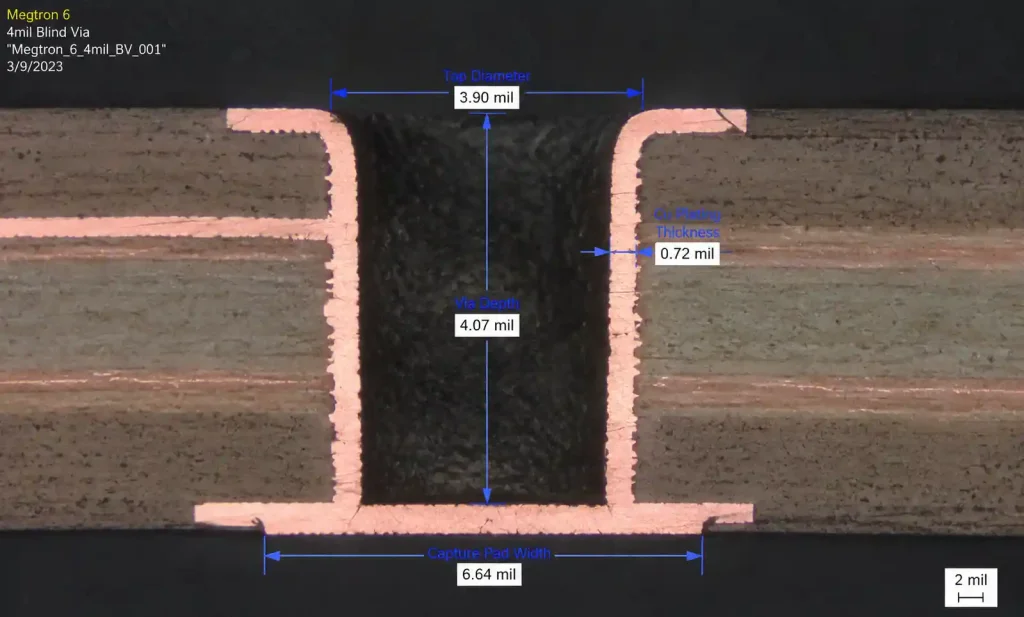
Via aspect ratios follow standard IPC-6012 Class 3 rules: we routinely achieve 12:1 (0.15mm drill through 1.8mm board thickness) with reliable plating. Laser microvia formation (CO2 or UV) works without parameter changes—our 4-mil blind vias from L1 to L2 on 3-mil RCC (resin-coated copper) show 100% capture pad yield. Some legacy shops struggle with PTFE because it requires mechanical drilling only; Megtron 6’s epoxy base supports both mechanical and laser processes.
Copper peel strength exceeds 1.2 N/mm after 6 reflow cycles, meeting aerospace specs (IPC-6012DS). We’ve never experienced a pad cratering failure in drop testing (JESD22-B111) on Megtron 6 with Panasonic’s VLP-grade foil (very low profile), unlike two instances on mid-tier FR-4 with standard RTF (reverse-treated foil) under identical conditions (1500G, 0.5 ms half-sine shock).
For buried resistor integration (common in impedance-matching networks for 50G+ signals), Megtron 6 supports standard resistive films (Ohmega Ohmega-Ply) laminated between L2-L3 without compatibility issues. The material’s stable Dk ensures that embedded resistor tolerance (±15% typical) doesn’t degrade further due to substrate variation—critical when you’re trimming 78-ohm series terminations for 100-ohm differential lines.
7. Cost Structure: When the Premium Makes Sense
Megtron 6 raw laminate pricing runs 2.2–2.8× standard FR-4 by area ($/sq ft), depending on thickness and copper weight. For a typical 8-layer, 12″×18″ panel (yielding 8× 4″×6″ boards), material delta is approximately $45 per panel. At 5,000-unit production volume, this translates to $0.56 per board material adder. However, total NRE shifts based on yield and rework:
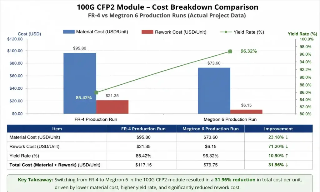
On a recent 100G CFP2 optical module (12-layer HDI, 1-2-1 microvia structure), we compared FR-4 vs. Megtron 6:
- FR-4 path: Lower material cost ($8.20/board), but 18% electrical test failures due to insertion loss (eye mask violations). Rework cost $22 per board, yielding total $10.16/board averaged across production.
- Megtron 6 path: Higher material cost ($11.40/board), 4% electrical failures (primarily assembly defects, not substrate loss). Rework cost $22 per board, yielding total $11.68/board averaged.
The Megtron 6 premium was $1.52/board (15% adder), but it eliminated a redesign cycle that would have cost 12 weeks schedule slip plus $25K NRE for re-layout and re-spin. For time-to-market-sensitive products (telecom infrastructure launch windows), this tradeoff favors Megtron 6.
Cost breakeven analysis: If your design has sufficient margin with FR-4 or mid-loss laminates (e.g., 25GBASE-CR1 over 3 meters of passive copper, where you have 16 dB channel budget), Megtron 6 adds cost without performance benefit. Use it when:
- Insertion loss is within 3 dB of your channel budget ceiling
- You’re eliminating retimers/repeaters (each retimer IC = $12–$18 and 1.2W)
- Service life > 10 years requires conservative aging margins
- Qualification testing has zero-fail requirements (aerospace, medical)
8. Material Selection Framework for Your Next Design
Use Megtron 6 when:
- Data rates ≥ 25 Gbps (NRZ) or ≥ 50 Gbps (PAM4) with trace lengths > 6 inches
- Operating frequency > 15 GHz (5G FR2 mmWave, 60 GHz WiGig, automotive radar)
- Link budget analysis shows < 4 dB margin with standard materials
- Thermal cycling requirements exceed 1,000 cycles (−40°C to +125°C)
- Production volumes justify 15–30% total cost adder for improved yield
Stick with enhanced FR-4 (Isola, Shengyi mid-loss) when:
- Maximum data rate ≤ 10 Gbps and trace lengths < 10 inches
- Cost pressure dominates (consumer IoT, low-margin appliances)
- Ambient temperature range is controlled (0°C to +50°C indoor)
- Your fab supplier lacks Megtron 6 qualification or experience
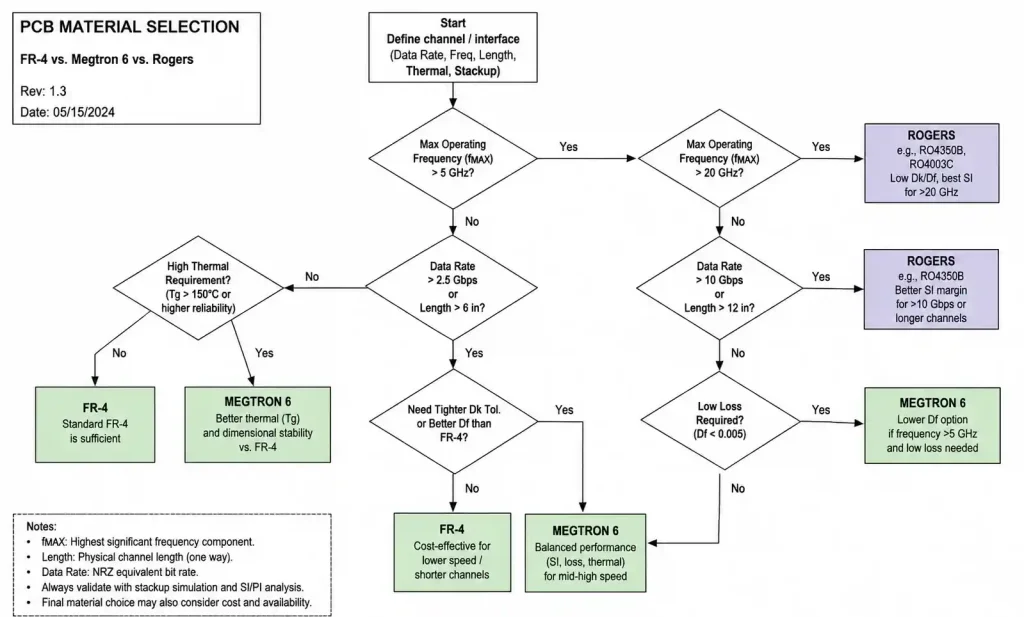
Consider Rogers or PTFE when:
- Operating frequency > 40 GHz (77 GHz automotive radar, E-band backhaul)
- Dk stability requirements are tighter than ±0.05 (phased array antennas)
- Your design budget and fabrication partner support premium exotics
In our 56G PAM4 evaluation for next-gen switches, we conducted a head-to-head bake-off: 20-inch backplane channels on three materials (FR-4, Megtron 6, Rogers 4350B). At 28 GHz (Nyquist), Megtron 6 delivered 94% of Rogers’ performance (13.2 dB loss vs. 12.5 dB) while maintaining FR-4’s process compatibility. For products shipping in volume—where supply chain resilience and second-source options matter as much as raw specs—Megtron 6 occupies the pragmatic middle ground.