Automotive LED Applications: Metal Core PCB Thermal Management Solutions
Automotive LED lighting systems generate significant heat in compact spaces, making thermal management critical for performance and reliability. Metal Core PCBs (MCPCBs) provide superior heat dissipation compared to standard FR4 boards, but effective thermal design requires understanding material properties, layer stackup choices, and automotive qualification requirements. This guide covers the essential design parameters, material selection criteria, and DFM considerations for automotive LED applications using MCPCBs.
Table of Contents
- Why thermal management matters in automotive LED applications
- Metal Core PCB construction and thermal performance fundamentals
- Material selection: aluminum vs copper cores and dielectric choices
- Critical design parameters for automotive LED MCPCBs
- Automotive qualification requirements and reliability considerations
- DFM guidelines and common manufacturing pitfalls
- FAQ
- Conclusion and next steps
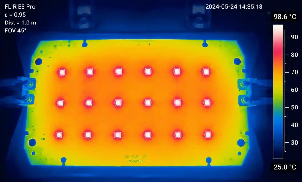
1. Why thermal management matters in automotive LED applications
Automotive LED modules operate in harsh environments with ambient temperatures ranging from -40°C to +125°C, while the LED junction itself can reach 150°C or higher under normal operation. Poor thermal management accelerates LED degradation, causing color shift, reduced luminous output, and premature failure. For headlamp assemblies rated at 50,000+ hours, maintaining junction temperature below the manufacturer’s specification is essential.
Standard FR4 PCBs have thermal conductivity of only 0.3-0.4 W/mK, creating thermal bottlenecks between high-power LEDs and the heat sink. Metal Core PCBs solve this by incorporating an aluminum or copper base layer with thermal conductivity of 1.0-8.0 W/mK or higher, directly transferring heat to the mechanical chassis or external cooling system.
The thermal resistance from LED junction to ambient (RθJA) determines the steady-state temperature rise. In automotive applications, reducing RθJA by even 2-3°C/W can extend LED lifespan by 30-50% under thermal cycling stress. MCPCB design directly impacts the thermal resistance path through proper material selection, copper thickness, and thermal via placement.
Critical factors in automotive LED thermal design include the LED package thermal pad size, solder joint quality, dielectric layer thermal impedance, and metal core thickness. Each interface adds thermal resistance, so minimizing these resistances through proper design is critical for long-term reliability in AEC-Q102 qualified assemblies.
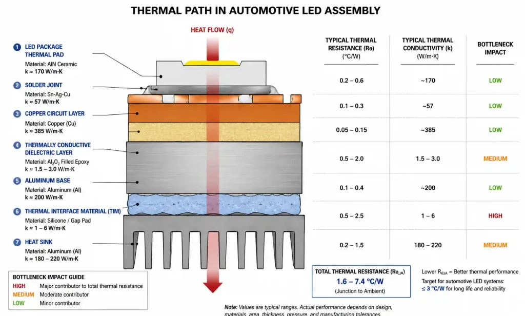
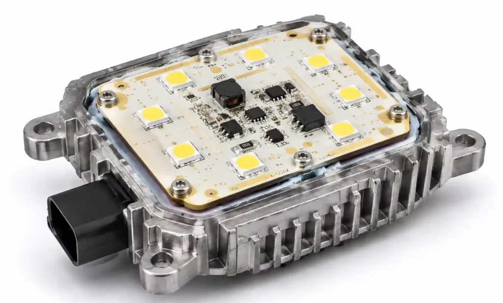
2. Metal Core PCB construction and thermal performance fundamentals
A typical MCPCB consists of four layers: circuit layer (copper), thermally conductive dielectric, metal base (aluminum or copper), and optional bottom coating. The circuit layer carries electrical traces and pads, while the dielectric layer provides electrical isolation with controlled thermal impedance. The metal base serves as both mechanical support and primary heat spreader.
The thermal performance of an MCPCB is characterized by its thermal resistance in °C·cm²/W or thermal conductivity in W/mK. A high-performance automotive MCPCB typically uses a dielectric layer with thermal conductivity of 2.0-4.0 W/mK and thickness of 50-100 μm, resulting in thermal impedance below 1.0°C·cm²/W. Lower thermal impedance allows faster heat transfer from LED pads to the metal core.
The metal base thickness ranges from 1.0 mm to 3.0 mm depending on mechanical requirements and thermal mass needed. Thicker bases provide better heat spreading but increase weight and material cost. For automotive headlamps, 1.5-2.0 mm aluminum bases balance thermal performance with mechanical rigidity for vibration resistance per AEC-Q200 Grade 1 requirements.
Copper thickness on the circuit layer typically ranges from 1 oz (35 μm) to 3 oz (105 μm). Thicker copper improves current carrying capacity and heat spreading within the circuit layer, which is important for parallel LED strings or high-current driver circuits. However, thicker copper increases etching undercut and minimum feature size, requiring DFM adjustments.
The thermal path efficiency depends on minimizing interface resistances. Solder joints between LED thermal pads and MCPCB pads should have full wetting coverage. The dielectric layer must be uniformly bonded to both copper and metal base without voids. Any air gaps or delamination significantly increases thermal resistance and creates hot spots.
3. Material selection: aluminum vs copper cores and dielectric choices
Selecting the right base metal and dielectric combination determines both thermal performance and manufacturing cost. Aluminum cores are standard for most automotive LED applications due to their favorable balance of thermal conductivity (120-200 W/mK), weight, machinability, and cost. Copper cores offer higher thermal conductivity (380-400 W/mK) but cost 3-5x more and add significant weight.
| Property | Aluminum 5052 | Aluminum 6061 | Copper C11000 |
|---|---|---|---|
| Thermal conductivity (W/mK) | 138 | 167 | 391 |
| Coefficient of thermal expansion (ppm/°C) | 23.8 | 23.6 | 17.0 |
| Density (g/cm³) | 2.68 | 2.70 | 8.94 |
| Cost relative to Al 5052 | 1.0x | 1.2x | 4.5x |
| Machinability | Good | Excellent | Good |
| Typical automotive use | Standard LED modules | High-power headlamps | Ultra-high power or RF |
Aluminum 6061 is preferred for automotive applications requiring CNC machining of complex mounting features or integrated heat sinks. Its slightly higher thermal conductivity and excellent machinability justify the modest cost premium for headlamp housings with integrated driver boards.
Copper cores are reserved for ultra-high power LEDs (>5W per LED) or applications where board space is extremely limited and maximum heat spreading is critical. The higher CTE mismatch between copper (17 ppm/°C) and ceramic LED packages (6-8 ppm/°C) requires careful mechanical design to avoid solder joint fatigue under thermal cycling.
The dielectric layer material significantly impacts thermal performance. Standard epoxy-based dielectrics offer 1.0-2.0 W/mK thermal conductivity at low cost. High-performance ceramic-filled dielectrics reach 3.0-4.0 W/mK but cost 2-3x more. For automotive applications, dielectric breakdown voltage must exceed 2500 VAC for safety compliance.
| Dielectric Type | Thermal Conductivity (W/mK) | Dielectric Strength (kV) | Typical Thickness (μm) | Automotive Grade | Cost Multiplier |
|---|---|---|---|---|---|
| Epoxy resin | 1.0-1.5 | 2.5-3.0 | 75-100 | Yes | 1.0x |
| Ceramic-filled epoxy | 2.0-2.5 | 3.0-3.5 | 60-80 | Yes | 1.5x |
| High thermal ceramic | 3.0-4.0 | 3.5-4.5 | 50-75 | Yes | 2.5x |
| Polyimide-based | 1.5-2.0 | 4.0-5.0 | 50-100 | Limited | 1.8x |
For automotive headlamps and tail lamps, ceramic-filled epoxy dielectrics at 75 μm thickness provide the best balance of thermal performance, electrical isolation, and cost. High thermal ceramic dielectrics are specified only when junction temperature targets cannot be met with standard materials, typically in compact LED arrays above 20W total power.
4. Critical design parameters for automotive LED MCPCBs
Designing an automotive LED MCPCB requires attention to copper weight, pad geometry, thermal via strategy, and electrical isolation clearances. Unlike standard PCBs, MCPCBs cannot use through-hole vias to the base layer due to the dielectric isolation requirement, so thermal management relies on surface area contact and lateral heat spreading.
The LED thermal pad should match or slightly exceed the LED package thermal pad dimensions. For mid-power LEDs (0.5-1.5W), typical pad sizes are 3×3 mm to 5×5 mm. High-power LEDs (3-5W) require 7×7 mm or larger thermal pads. The pad area directly contacts the dielectric layer, so maximizing pad size within layout constraints reduces thermal impedance.
Copper thickness selection balances electrical conductivity and thermal spreading. For LED arrays with total current below 3A, 1 oz copper is sufficient. High-power modules with 5-10A current or requiring enhanced heat spreading should specify 2 oz copper. Trace width for LED power delivery should follow IPC-2152 current carrying calculations with 20°C temperature rise limit.
| Design Parameter | Standard LED (0.5-1.5W) | High Power LED (3-5W) | Ultra-High Power (>5W) |
|---|---|---|---|
| LED thermal pad size | 3×3 to 4×4 mm | 5×5 to 7×7 mm | 8×8 mm or larger |
| Recommended copper weight | 1 oz (35 μm) | 2 oz (70 μm) | 3 oz (105 μm) |
| Minimum trace width (power) | 0.3 mm | 0.5 mm | 0.8 mm |
| Clearance to board edge | 3.0 mm | 3.0 mm | 3.0 mm |
| Solder mask over thermal pad | No | No | No |
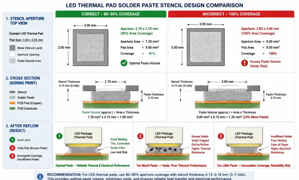
| Thermal pad solder paste coverage | 80-90% | 80-90% | 80-90% |
Electrical isolation clearances must meet automotive voltage requirements. For 12V systems, maintain 0.5 mm minimum clearance between traces. For 48V systems, increase to 1.0 mm minimum. High voltage LED drivers (>60V) require 1.5 mm clearance and may need conformal coating for additional isolation.
Solder mask should not cover LED thermal pads, as this adds thermal resistance. Use solder mask defined pads with 0.1-0.15 mm solder mask expansion around the thermal pad perimeter. This prevents solder bridging to adjacent traces while maintaining full thermal contact between LED and copper pad.
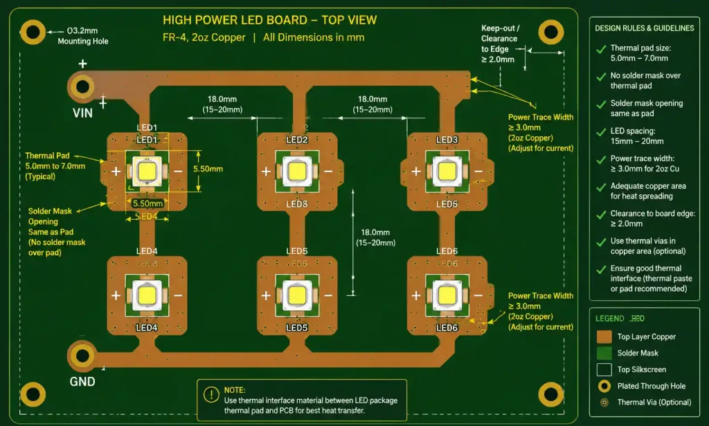
Thermal management for multi-LED arrays requires careful heat spreading design. Space LEDs at least 10-15 mm apart for mid-power LEDs or 15-20 mm for high-power LEDs to prevent thermal crosstalk. Copper fill areas between LEDs improve lateral heat spreading before heat transfers through the dielectric layer to the metal base.
5. Automotive qualification requirements and reliability considerations
Automotive LED modules must pass AEC-Q102 qualification for LED components and meet vehicle manufacturer’s specific requirements for thermal cycling, vibration, and humidity resistance. The MCPCB design directly impacts the assembly’s ability to survive these stress tests without LED performance degradation or solder joint failure.
Thermal cycling per AEC-Q102 typically requires 1000 cycles from -40°C to +125°C with 30-minute dwell times. The CTE mismatch between aluminum base (23.8 ppm/°C), copper circuit layer (17 ppm/°C), and ceramic LED packages (6-8 ppm/°C) creates mechanical stress during temperature transitions. Thicker dielectric layers (75-100 μm) provide mechanical compliance to reduce stress, but this trades off against thermal performance.
For LED modules mounted to chassis heat sinks, the thermal interface material (TIM) between MCPCB base and heat sink adds thermal resistance. Typical TIMs add 0.2-0.5°C·cm²/W thermal impedance. Using thermal grease or phase-change materials provides better interface than thermal pads, but requires controlled torque during assembly to achieve optimal bond line thickness of 50-100 μm.
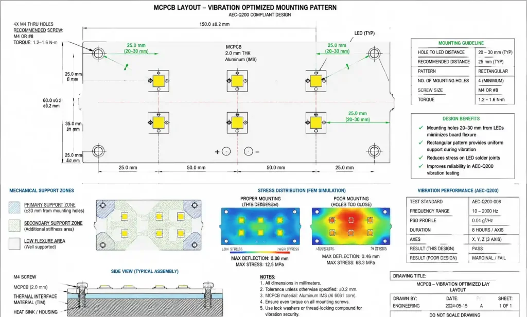
Vibration testing per AEC-Q200 applies sinusoidal vibration up to 20G and random vibration per vehicle-specific profiles. The MCPCB must be mounted with sufficient mechanical support to prevent flexure that could crack solder joints. Mounting hole placement should follow a rectangular pattern with holes 20-30 mm from LED positions to minimize board deflection under vibration.
Moisture resistance testing (85°C/85% RH for 1000 hours) stresses the dielectric layer adhesion and LED package sealing. Conformal coating provides additional protection, but the coating must be compatible with high operating temperatures (>100°C) and not degrade thermal performance. Parylene or silicone-based coatings are common for automotive LED assemblies.
The expected LED lifetime in automotive applications is 15,000-50,000 hours depending on the application. Headlamps require longest life, while interior accent lighting has lower requirements. Maintaining LED junction temperature below 100°C under worst-case ambient conditions (40°C + solar loading) is critical for achieving lifetime targets with less than 30% lumen depreciation (L70).
6. DFM guidelines and common manufacturing pitfalls
Manufacturing MCPCBs for automotive applications requires tighter process controls than standard PCBs due to the thermal performance requirements and the metal base handling challenges. Understanding common DFM issues prevents costly respins and qualification delays.
The metal base thickness creates challenges for routing and milling operations. Standard CNC routing bits can burr or deform aluminum edges if feed rates are too aggressive. Specify board edge finish requirements in manufacturing drawings, particularly for boards with exposed metal edges that contact heat sinks or chassis ground points.
Dielectric layer voids are a critical defect that significantly reduces thermal performance. Voids typically occur from trapped air during lamination or contamination on the aluminum surface. Reputable MCPCB manufacturers use vacuum lamination processes and strict surface preparation protocols. Require thermal impedance testing on production lots to verify consistent dielectric bonding quality.
Solder paste volume for LED thermal pads requires optimization. Too much paste creates voids during reflow as flux volatiles escape. Too little paste results in incomplete thermal pad coverage. Type 4 or Type 5 solder paste with 80-90% stencil aperture coverage provides optimal results. Consider using solder preforms for large thermal pads above 7×7 mm to ensure complete wetting.
| DFM Check Item | Requirement | Risk if Violated | Manufacturing Capability Range |
|---|---|---|---|
| Minimum trace width/spacing | 0.15/0.15 mm | Etching defects, shorts | 0.1/0.1 mm to 0.3/0.3 mm |
| Minimum pad diameter | 0.8 mm | Insufficient solder adhesion | Standard: 0.6 mm, Min: 0.4 mm |
| Copper weight tolerance | ±10% | Current capacity, impedance | 1-3 oz typical |
| Dielectric thickness tolerance | ±15 μm | Thermal impedance variation | 50-100 μm typical |
| Metal base thickness tolerance | ±0.1 mm | Mechanical fit issues | 1.0-3.0 mm typical |
| Board thickness tolerance | ±0.15 mm | Assembly clearance issues | Total stackup dependent |
| Solder mask registration | ±0.1 mm | Pad exposure issues | ±0.075 mm achievable |
Copper weight tolerance impacts both thermal and electrical performance. Verify that the manufacturer’s process can maintain ±10% tolerance on copper thickness, particularly for 2 oz and 3 oz copper weights where etching control becomes more challenging. Thicker copper also increases undercut, so minimum trace width specifications should account for this.
Panelization strategy affects both cost and quality. Individual boards under 100×100 mm should be panelized for efficient manufacturing. Use tab routing or V-score separation, but avoid V-score lines that cross LED mounting areas, as this can create mechanical stress points. Maintain 5 mm minimum border from board edge to first LED pad for handling clearance.
Testing requirements should include electrical testing (flying probe or fixture) and thermal impedance spot checks. Some manufacturers offer thermal imaging verification after sample assembly to confirm proper heat transfer. For high-volume production, negotiate inclusion of thermal impedance measurement on a statistical sampling basis to catch process variations early.
The surface finish choice impacts both solderability and long-term reliability. ENIG (Electroless Nickel Immersion Gold) is standard for automotive applications due to excellent shelf life and gold wire bondability if needed. OSP (Organic Solderability Preservative) costs less but has limited shelf life and requires careful handling. Avoid HASL (Hot Air Solder Leveling) on MCPCBs as the thermal shock during application can stress the dielectric bonding.
7. FAQ
What is the typical thermal impedance of an automotive-grade MCPCB?
Automotive MCPCBs typically achieve 0.5-1.2°C·cm²/W thermal impedance depending on dielectric material and thickness. High-performance ceramic-filled dielectrics at 50-75 μm thickness reach 0.5-0.8°C·cm²/W. Standard epoxy dielectrics at 75-100 μm provide 0.8-1.2°C·cm²/W. Lower values indicate better heat transfer from LED to metal base.
Can I use thermal vias in a Metal Core PCB design?
No, traditional plated through-hole thermal vias cannot penetrate through the dielectric layer to the metal base, as this would create an electrical short. The dielectric layer must maintain electrical isolation. Heat transfer relies on surface contact area between LED thermal pads and the copper layer, then through the dielectric to the aluminum base. Maximize LED pad size instead.
How do I calculate the junction temperature for my LED on an MCPCB?
Junction temperature TJ = TA + (P × RθJA), where TA is ambient temperature, P is LED power dissipation in watts, and RθJA is total thermal resistance from junction to ambient. RθJA = RθJC + RθCS + RθSA, combining LED package resistance, MCPCB thermal impedance, and heat sink resistance. Verify TJ stays below LED manufacturer’s maximum rating under worst-case conditions.
What copper thickness should I specify for a 3W LED array?
For LEDs in the 3-5W range, specify 2 oz (70 μm) copper. This provides adequate current carrying capacity for typical LED drive currents of 500-1000 mA per LED and improves lateral heat spreading before heat transfers through the dielectric. For lower power LEDs under 1.5W, 1 oz copper is sufficient. Above 5W per LED, consider 3 oz copper.
Do MCPCBs require different reflow profiles than standard PCBs?
MCPCB reflow profiles should follow LED manufacturer recommendations, typically 260°C peak temperature with 30-60 second time above liquidus. The metal base acts as a large thermal mass, so preheat zone may require 10-20 seconds longer to bring the entire board to temperature uniformly. Avoid excessive time above liquidus as this can stress the dielectric bonding.
What is the difference between aluminum 5052 and 6061 for automotive LED applications?
Aluminum 6061 offers higher thermal conductivity (167 vs 138 W/mK) and better machinability for CNC operations like mounting holes and heat sink features. It costs about 20% more than 5052. Use 6061 for headlamp assemblies requiring integrated heat sinks or complex mechanical features. Use 5052 for cost-sensitive applications like tail lamps where standard mounting is sufficient.
How thick should the metal base be for vibration resistance?
For automotive AEC-Q200 Grade 1 vibration requirements, use 1.5-2.0 mm aluminum base thickness for boards up to 100×100 mm. Larger boards may require 2.0-2.5 mm thickness to prevent flexure under vibration that could crack LED solder joints. Thicker bases also improve heat spreading but add weight and cost.
Can MCPCBs be wave soldered or must they use reflow?
MCPCBs are typically reflow soldered due to LED package requirements and the thermal mass of the metal base. Wave soldering subjects the dielectric layer to extended thermal exposure that can degrade bonding adhesion. Reflow soldering with controlled profiles is the standard approach for LED assembly on MCPCBs in automotive applications.
8. Conclusion and next steps
Effective thermal management is critical for automotive LED reliability and lifetime. Metal Core PCBs provide the thermal performance required for high-power LED applications, but success depends on proper material selection, design parameter optimization, and DFM awareness. For automotive headlamps and high-reliability applications, specify ceramic-filled dielectric materials with thermal conductivity above 2.0 W/mK, use aluminum 6061 base metal for integrated mechanical features, and design LED thermal pads to maximize surface contact area.
Before submitting your automotive LED MCPCB design for manufacturing, verify that copper thickness matches your thermal and electrical requirements, confirm that isolation clearances meet your system voltage requirements, and review the DFM checklist to avoid common pitfalls like insufficient solder mask clearance or inadequate mechanical support under vibration.
Our engineering team specializes in automotive LED thermal design and can provide free DFM review of your MCPCB layout. Upload your design files to receive thermal performance analysis, manufacturing feasibility assessment, and optimization recommendations to meet your junction temperature and reliability targets. For prototype or production quotes on automotive-qualified MCPCBs, contact our CAM engineering team with your specifications.