How to Select Conformal Coating Material for Your Project
Selecting the right conformal coating material is critical for PCB reliability in harsh environments. This guide walks you through material types, performance characteristics, application requirements, and selection criteria based on real-world engineering experience. Whether you’re designing automotive electronics, medical devices, or industrial controls, understanding conformal coating properties will help you avoid field failures and costly rework.
What Is Conformal Coating and Why Material Selection Matters
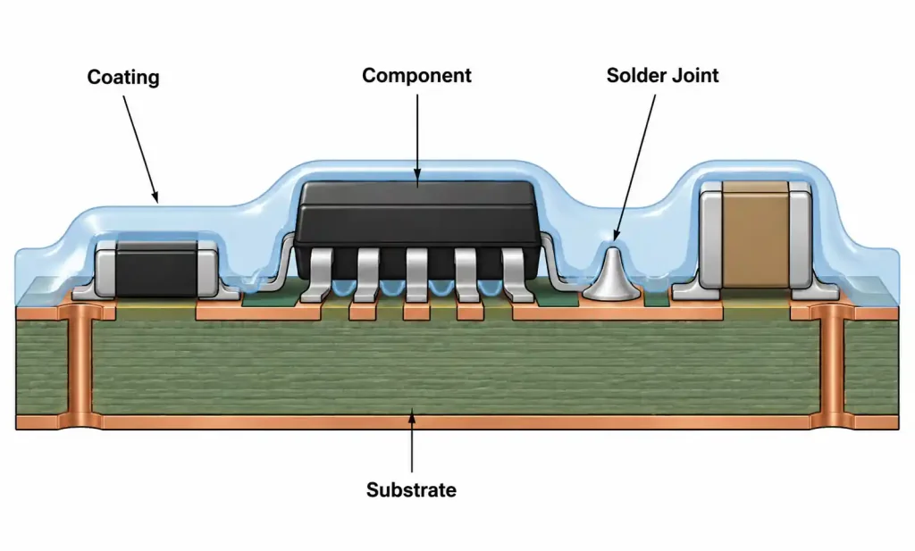
Conformal coating is a thin protective polymer layer applied to PCB assemblies to shield components and traces from moisture, dust, chemicals, temperature extremes, and mechanical stress. The coating “conforms” to the board topology, covering components, solder joints, and exposed copper while maintaining electrical insulation.
Material selection directly impacts long-term reliability. A coating that performs well in controlled lab conditions may fail in automotive underhood temperatures, marine salt spray, or aerospace thermal cycling. Engineers often underestimate how environmental exposure, thermal expansion mismatch, and chemical compatibility affect coating adhesion and dielectric strength over the product’s operational life.
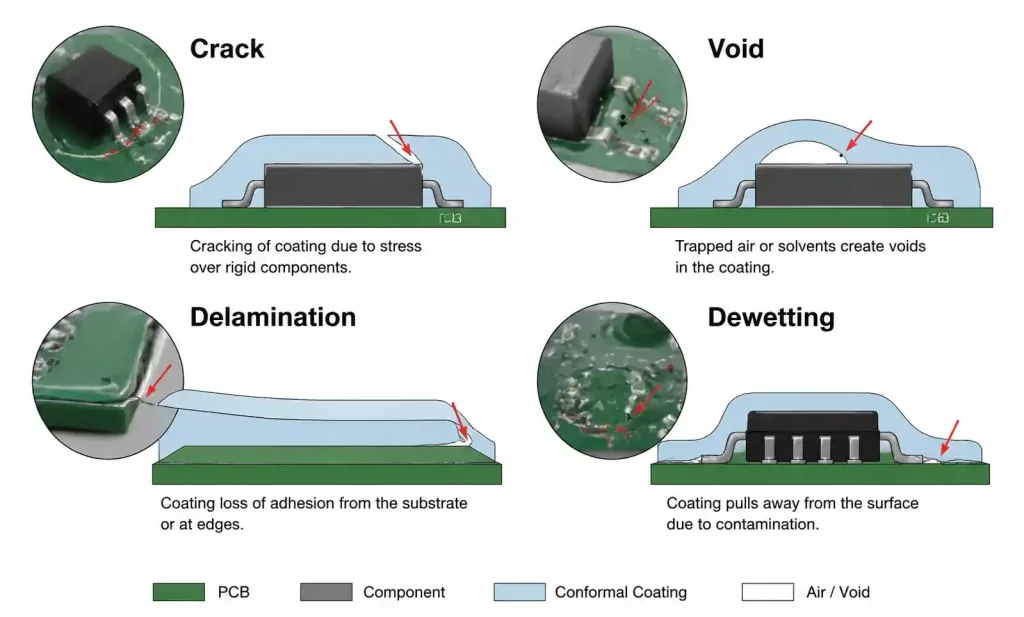
The wrong material choice leads to delamination, cracking, moisture ingress at connector zones, and ultimately field failures. This is particularly critical for Class 3 electronics per IPC-A-610, where reliability requirements are stringent. Understanding material chemistry, cure mechanisms, and application methods allows you to match coating properties to your specific environmental stress profile and manufacturing constraints.
Five Main Types of Conformal Coating Materials
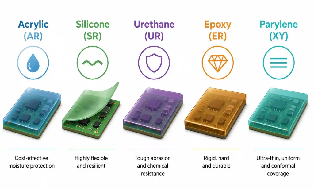
The industry recognizes five primary conformal coating chemistries, each with distinct performance characteristics and trade-offs.
Acrylic (AR)
Acrylic coatings are solvent-based, single-component materials that cure through solvent evaporation. They offer the easiest rework capability because they dissolve readily in solvents like isopropyl alcohol or specialized strippers. Acrylic provides good moisture resistance and dielectric strength, making it suitable for consumer electronics and moderate-environment industrial applications.
The main limitation is lower chemical resistance compared to other chemistries. Acrylic coatings can soften or degrade when exposed to strong solvents, fuels, or hydraulic fluids. They also have a lower operating temperature ceiling, typically around 125°C continuous exposure. However, their fast cure time and room-temperature application make them economical for high-volume production.
Silicone (SR)
Silicone coatings excel in extreme temperature environments, maintaining flexibility from -65°C to +200°C. The silicone polymer chain structure provides excellent thermal stability and resistance to thermal cycling. This makes silicone the preferred choice for automotive underhood electronics, aerospace systems, and LED drivers where heat dissipation is critical.
Silicone’s high flexibility accommodates thermal expansion differences between the coating, PCB substrate, and components. However, this same flexibility means lower abrasion resistance compared to harder coatings. Silicone is also difficult to rework because it does not dissolve easily in common solvents. You typically need to mechanically remove it or use specialized peeling techniques. Silicone contamination can interfere with subsequent adhesive bonding or secondary coating operations, requiring careful masking and process control.
Urethane (UR)
Urethane coatings, also called polyurethane, provide the best overall chemical resistance and abrasion resistance. They form a hard, durable film that protects against solvents, fuels, oils, and cleaning agents. This makes urethane ideal for industrial controls, automotive electronics exposed to fluids, and military equipment.
Urethane coatings cure through moisture reaction, forming a crosslinked polymer network. This gives excellent adhesion and mechanical strength but makes rework challenging. Urethane is harder to remove than acrylic but easier than silicone. The main drawback is moisture sensitivity during cure—high humidity can cause surface defects or incomplete cure. Urethane also has limited flexibility compared to silicone, which can lead to cracking under severe thermal cycling if the coating thickness or substrate materials are not properly matched.
Epoxy (ER)
Epoxy coatings offer the highest dielectric strength and chemical resistance, making them suitable for high-voltage circuits and applications requiring maximum environmental protection. Epoxy is a two-component system that cures through chemical crosslinking, producing a rigid, impermeable barrier.
The rigidity that provides excellent protection also makes epoxy the most difficult to rework. Removal typically requires grinding or chemical strippers that can damage components. Epoxy’s brittleness under thermal cycling limits its use in applications with wide temperature swings. However, for static high-voltage environments or permanent encapsulation where rework is not anticipated, epoxy delivers unmatched protection. Epoxy coatings are common in power supplies, high-reliability industrial sensors, and outdoor telecommunications equipment.
Parylene (XY)
Parylene is a vapor-deposited polymer applied through chemical vapor deposition (CVD) in a vacuum chamber. Unlike liquid coatings, parylene forms a perfectly uniform, pinhole-free film with thickness control down to microns. This gives parylene superior barrier properties and dielectric performance.
Parylene excels in medical implants, aerospace avionics, and critical military electronics where reliability cannot be compromised. The CVD process ensures complete coverage of complex geometries, including under low-clearance components. However, parylene requires specialized equipment, making it the most expensive coating option. Rework is extremely difficult, typically requiring laser ablation or plasma etching. Parylene is also sensitive to UV exposure, which can degrade the polymer over time unless UV-stabilizing additives are incorporated.
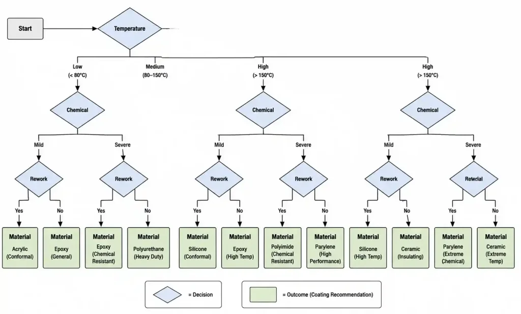
Key Selection Criteria: Environment, Performance, and Process
Choosing the right conformal coating requires evaluating multiple criteria that affect both performance in service and manufacturability.
Environmental Exposure
The operating environment drives material selection more than any other factor. Temperature range, humidity, chemical exposure, and mechanical stress define the coating’s required performance envelope. For automotive underhood applications, sustained temperatures above 130°C rule out acrylic and require silicone or high-temperature urethane. Marine environments with salt spray and condensation demand coatings with proven salt fog test performance per ASTM B117, pointing toward urethane or parylene.
Industrial equipment exposed to hydraulic fluids, lubricants, or solvents requires urethane or epoxy. Consumer electronics in indoor environments can typically use acrylic, balancing cost and adequate protection. When multiple environmental stressors are present, prioritize the most severe condition. For example, if a board sees both thermal cycling and chemical exposure, chemical resistance may be more critical since coating failure from chemical attack happens faster than thermal fatigue.
Electrical Performance
Dielectric strength, insulation resistance, and dielectric constant are key electrical parameters. High-voltage circuits require coatings with breakdown voltage above 1500V/mil, which points to epoxy or parylene. For RF or high-frequency circuits, low dielectric constant and loss tangent are critical to minimize signal attenuation. Parylene and certain silicones have the lowest dielectric constant, making them suitable for RF shielding and antenna circuits.
Insulation resistance must remain stable across the operating temperature and humidity range. Moisture absorption degrades insulation resistance, so coatings for humid environments need low moisture permeability. IPC-CC-830 provides standardized test methods for measuring these properties, and your coating supplier should provide test data showing performance across your operating conditions.
Rework and Repair Requirements
Rework capability directly impacts production yield and field service costs. If you anticipate high rework rates during development or need to replace components in the field, acrylic is the clear choice. Urethane offers a middle ground—it can be removed with solvents and mechanical methods but requires more effort than acrylic. Silicone and epoxy are progressively harder to rework, and parylene is nearly impossible without specialized equipment.
Consider the component types on your board. Fine-pitch BGAs, connectors, and switches under coating may need future access. Selective coating with maskants can preserve rework areas, but this adds process complexity. For high-reliability applications where rework is rare, the difficulty of removal may be acceptable in exchange for superior protection.
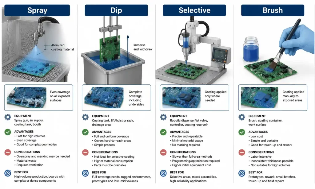
Application Method and Production Throughput
Conformal coatings can be applied by brush, spray, dip, or selective robotic dispensing. Acrylic, silicone, and urethane work with all methods, while epoxy’s higher viscosity and pot life limit spray and selective coating. Parylene requires dedicated CVD chambers and batch processing, which impacts throughput.
For high-volume production, spray or dip coating offers speed but requires careful masking and may waste material. Selective coating provides precise control over coating areas, reducing masking needs and material consumption, but adds cycle time. The coating’s cure mechanism also affects throughput. Acrylic dries in minutes at room temperature, while urethane may need 24-48 hours for full cure. UV-cure acrylics offer instant cure but require UV-transparent components and special equipment.
Cost Considerations
Material cost ranges from acrylic at the low end to parylene at the high end, but total cost of ownership includes application equipment, labor, rework, and failure rates. Acrylic may have the lowest material cost but higher field failure rates in harsh environments. Parylene has the highest material and equipment cost but near-zero field failures in demanding applications.
Factor in the cost of rework. If production yield is low and rework is frequent, the cost of removing urethane or silicone can exceed the savings from using a cheaper material. For field failures, the cost of warranty claims, returns, and brand damage often dwarfs the initial material cost difference.
Material Comparison Table by Application Scenario
| Application Scenario | Recommended Material | Temperature Range (°C) | Chemical Resistance | Rework Difficulty | Typical IPC Class |
|---|---|---|---|---|---|
| Consumer electronics (indoor) | Acrylic (AR) | -40 to +125 | Moderate | Easy | Class 2 |
| Automotive underhood | Silicone (SR) | -65 to +200 | Good | Difficult | Class 3 |
| Industrial controls (chemical exposure) | Urethane (UR) | -55 to +130 | Excellent | Moderate | Class 2/3 |
| High-voltage power supply | Epoxy (ER) | -40 to +150 | Excellent | Very Difficult | Class 3 |
| Medical implantable device | Parylene (XY) | -65 to +200 | Excellent | Extremely Difficult | Class 3 |
| Marine electronics (salt spray) | Urethane (UR) or Parylene (XY) | -40 to +85 | Excellent | Moderate to Difficult | Class 3 |
| LED drivers (thermal management) | Silicone (SR) | -40 to +150 | Moderate | Difficult | Class 2 |
| Aerospace avionics | Parylene (XY) or Urethane (UR) | -65 to +125 | Excellent | Difficult | Class 3 |
This table provides starting points for material selection based on common application environments. The temperature range reflects continuous operating temperature, not short-term excursions. Chemical resistance is rated against common industrial fluids, solvents, and cleaning agents. Rework difficulty reflects the effort required to remove the coating for component replacement without board damage.
When your application falls between categories, consider hybrid approaches. Some designs use urethane for primary protection with selective silicone coating over high-heat components. Others apply a thin acrylic base coat for electrical insulation followed by a thicker urethane topcoat for chemical resistance. These multi-layer strategies require careful material compatibility testing to ensure adhesion between layers.
Coating Thickness, Coverage, and IPC Standards
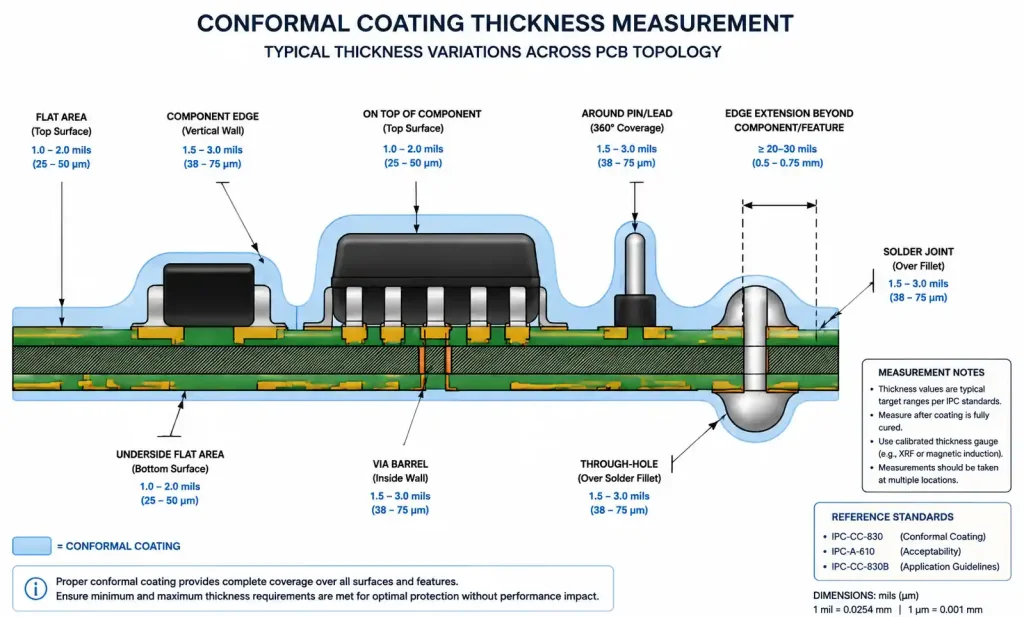
Coating thickness directly affects protection level, flexibility, and dielectric performance. IPC-A-610 and IPC-CC-830 provide acceptance criteria for coating quality and thickness.
Thickness Requirements
IPC-CC-830 recommends 1-3 mils (25-75 microns) for most applications. Thinner coatings reduce material cost and preserve component heat dissipation but offer less environmental protection. Thicker coatings improve barrier properties but increase stress at the coating-substrate interface during thermal cycling. For high-voltage isolation, thickness must be calculated based on required breakdown voltage and the coating’s dielectric strength, typically specified in volts per mil.
Coating thickness is rarely uniform across the board. Edges, component sides, and sharp features receive less material than flat surfaces. Automated optical inspection or cross-sectional analysis can verify thickness distribution, especially for critical areas like high-voltage creepage paths or connector interfaces.
Coverage Areas and Masking
IPC-A-610 defines acceptable coating coverage but allows selective coating to preserve areas requiring component access, solderability, or electrical contact. Common masked areas include connectors, test points, programming headers, switches, adjustment potentiometers, and heat sinks.
Masking methods include liquid maskants (peelable or dissolvable), tape, 3D-printed fixtures, and robotic programming for selective coating. Liquid maskants work well for low-volume prototype runs but add labor cost. For production, selective coating equipment programs nozzle paths to avoid restricted areas, eliminating manual masking but requiring CAD file preparation and process validation.
The coating edge must extend at least 0.5mm beyond the last component or trace that requires protection. Insufficient edge coverage allows moisture wicking under the coating through capillary action. Overspray onto connectors or masked areas requires rework, reducing production efficiency.
Inspection and Quality Control
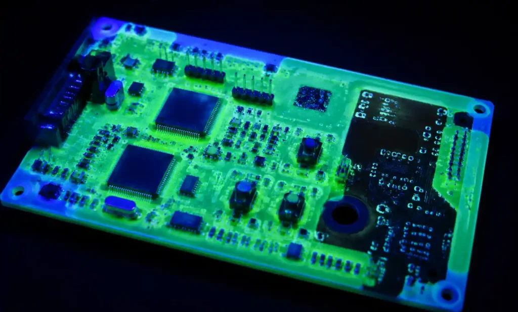
Visual inspection per IPC-A-610 looks for voids, pinholes, contamination, dewetting, and incorrect coverage. Fluorescent dyes added to the coating enable UV light inspection, making thin films and coverage gaps visible. Automated optical inspection systems can measure coating thickness using reflectance or fluorescence intensity if calibrated properly.
For Class 3 applications, destructive cross-sectional analysis verifies coating thickness, adhesion, and interface quality at solder joints and component leads. Salt fog testing per ASTM B117, humidity aging per IPC-TM-650, and thermal cycling verify long-term reliability. These tests should be completed during design validation, not after field failures occur.
Common Selection Mistakes and How to Avoid Them
Engineers frequently make predictable mistakes when selecting conformal coatings, often because they rely on datasheet comparisons without considering application-specific factors.
Mistake 1: Choosing Based on Cost Alone
Selecting the cheapest material without evaluating environmental requirements leads to field failures. A $0.10 per board savings on acrylic versus urethane becomes irrelevant when warranty claims cost $50 per return. Calculate total cost of ownership including expected failure rates, not just material cost per unit.
Mistake 2: Ignoring Thermal Expansion Mismatch
Rigid coatings like epoxy on flexible substrates or over components with high thermal expansion coefficients cause cracking during temperature cycling. This is particularly common with ceramic capacitors and large BGAs. Match coating flexibility to the substrate and component materials. Use finite element analysis for critical designs to predict stress concentrations.
Mistake 3: Inadequate Surface Preparation
Conformal coating adhesion depends on clean, dry, oxide-free surfaces. Residual flux, oils from handling, moisture, or oxidation cause dewetting and delamination. Follow IPC-CH-65 cleaning guidelines and verify surface cleanliness before coating. For no-clean flux processes, ensure the flux is compatible with the coating chemistry or remove it before coating.
Mistake 4: Not Testing Coating Compatibility with Components
Some conformal coatings attack specific component types. Acrylic and urethane solvents can damage polycarbonate lenses on LEDs or optical sensors. Silicone can outgas and contaminate sensitive components like relays or optics. Always test coating compatibility with representative components before production release.
Mistake 5: Applying Coating Too Thick
Excessive thickness traps stress and causes cracking, especially over tall components or at board edges. It also impedes heat dissipation from power components and can cause components to overheat. Follow the manufacturer’s recommended thickness range and use process controls to maintain consistency.
Mistake 6: Skipping Accelerated Life Testing
Datasheet properties represent fresh coatings under ideal conditions. Real-world performance degrades with thermal cycling, UV exposure, and moisture absorption. Conduct accelerated life testing that simulates your operating environment. For automotive, follow AEC-Q100 or AEC-Q200 qualification requirements. For industrial, use IPC-9701 or IEC 60068 environmental test standards.
FAQ
What is the difference between conformal coating and encapsulation?
Conformal coating is a thin (1-3 mils) protective film that conforms to board topography while allowing component visibility and rework. Encapsulation is a thick potting compound (several millimeters) that fully encases the assembly, providing maximum environmental protection but making rework nearly impossible. Use conformal coating when you need protection with rework access, and encapsulation when permanent sealing is required.
Can I apply conformal coating over no-clean flux residues?
It depends on the flux and coating chemistry. Some no-clean fluxes are designed to be coating-compatible and do not need removal. Others contain activators that remain corrosive or interfere with coating adhesion. Check the flux manufacturer’s compatibility data with your coating type. When in doubt, clean the board per IPC-CH-65 guidelines before coating.
How do I calculate required coating thickness for high-voltage isolation?
Divide the maximum working voltage by the coating’s dielectric strength (in volts per mil) and add a safety factor. For example, if you need 1000V isolation and use a coating rated at 1500V/mil, the minimum thickness is 1000/1500 = 0.67 mils. Apply a 2-3x safety factor for reliability, giving about 1.5-2 mils minimum. Also verify that creepage and clearance distances meet IPC-2221 requirements, as coating does not replace physical spacing for high voltage.
Which conformal coating has the best moisture resistance?
Parylene provides the best moisture barrier due to its pinhole-free, vapor-deposited structure. Among liquid coatings, urethane and epoxy offer better moisture resistance than acrylic or silicone. However, moisture resistance depends on coating thickness, cure quality, and edge sealing. A well-applied urethane coating often outperforms a poorly applied parylene coating.
How does conformal coating affect thermal management?
Conformal coatings add a thin insulating layer that slightly reduces heat dissipation from components. For low-power designs this is negligible, but for high-power components like MOSFETs, voltage regulators, or LEDs, coating can raise junction temperatures by 5-15°C depending on thickness and thermal conductivity. Silicone has the best thermal conductivity among conformal coatings. For critical thermal applications, mask heat sinks and high-power components, or use thermal interface materials in addition to coating.
Can I rework a PCB multiple times after coating?
Yes for acrylic, with proper solvent removal and reapplication. Urethane allows 1-2 rework cycles but becomes progressively harder to remove cleanly. Silicone and epoxy make multiple rework cycles impractical without board damage. Parylene typically cannot be reworked in production environments. If you anticipate frequent rework during development, use acrylic or design with selective coating that leaves rework areas uncoated.
What is the shelf life and storage requirement for conformal coatings?
Most liquid conformal coatings have 6-12 month shelf life when stored sealed at room temperature away from moisture and UV light. Two-part epoxies have shorter shelf life once mixed (hours to days). Acrylic and urethane are moisture-sensitive and should be kept tightly sealed. Expired coating may have increased viscosity, incomplete cure, or poor adhesion. Always check the manufacturer’s date code and storage recommendations.
How do I select coating color, and does it matter?
Conformal coatings are available in clear, red, blue, or green, often with UV-fluorescent dyes for inspection. Color choice is primarily for visual identification and inspection convenience. Clear coatings preserve board aesthetics for consumer products. Colored or fluorescent coatings make coverage verification easier during production QC. Some specifications require specific colors for identification purposes. Color does not significantly affect electrical or environmental performance.
Conclusion
Picking the right conformal coating is all about balancing protection, electricals, manufacturability, and cost. For most industrial and automotive jobs, urethane hits the sweet spot—good chemical and temperature resistance, plus you can still rework it. Silicone is your go‑to for extreme heat or cold where flexibility matters. Acrylic? Fine for consumer gear in controlled environments where cost and rework are top priorities.
For mission‑critical stuff—medical implants, aerospace avionics, military electronics—parylene is worth the extra cost because it just doesn’t fail. Epoxy has its niche too: maximum dielectric strength and chemical resistance, but forget about rework.
Start by defining your real environmental stress: temperature range, humidity, chemical exposure, vibration. Match that against material properties, then validate with accelerated life testing that mimics actual field conditions. Work with your coating supplier to dial in viscosity, cure profiles, and thickness for your specific board.Before you commit to production, run a DFM review that includes coating. Figure out what needs masking, make sure components have enough spacing for coating to penetrate, and verify your assembly leaves clean, dry surfaces for good adhesion.
Need help picking a coating? Send us your design specs and environmental requirements for a free recommendation and DFM review from our materials team.