Aerospace Radar Rigid-Flex PCB Design: IPC-6013 Class 3 Requirements and Material Selection Guide (2026)
Why Aerospace Radar Systems Demand Rigid-Flex PCB Technology
Aerospace radar systems operate under conditions that would destroy conventional PCB assemblies within hours. The combination of high-frequency signal transmission (X-band, Ku-band, or Ka-band), extreme vibration during flight, rapid thermal cycling from ground to altitude (-55°C to +125°C), and strict weight limitations creates a unique set of constraints that rigid-flex technology is uniquely positioned to address.
Traditional rigid PCB + cable assemblies introduce three critical failure modes:
| Failure Mode | Root Cause | Impact on Radar Performance |
|---|---|---|
| Connector intermittency | Vibration-induced fretting corrosion | Signal dropouts, false targets |
| Impedance discontinuity | Cable-to-board connector interfaces | Phase errors, degraded beam steering |
| Excessive weight | Cable harnesses and support structures | Reduced payload, shorter range |
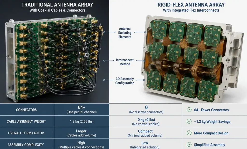
Each coaxial cable connection in a radar system adds approximately 0.5 dB insertion loss and creates impedance discontinuities that degrade phase accuracy in phased array antennas. In a 64-element phased array, eliminating 128 connectors reduces system insertion loss by 40–60 dB cumulative across all channels.
Rigid-flex construction eliminates these vulnerabilities by:
- Integrating flexible interconnect directly into the board stackup (replaces cables)
- Maintaining controlled impedance throughout the entire signal path
- Reducing part count by 40–60% compared to cable-connected assemblies
- Eliminating solder joints in high-vibration areas
- Reducing system weight by 20–35%
Engineering insight: For aerospace applications where every gram matters and reliability cannot be compromised, rigid-flex technology is not just an advantage—it is the only viable solution for modern radar systems.
Critical Design Parameters for Radar System Rigid-Flex PCBs
Designing rigid-flex PCBs for aerospace radar requires balancing RF performance, mechanical flexibility, and thermal management. The rigid sections house active components (power amplifiers, LNAs, processors) and provide structural support, while flexible sections route high-frequency signals between antenna elements or between RF modules and signal processing boards.
Impedance Control Requirements
For radar applications, trace impedance control is mission-critical. Most aerospace radar systems require:
| Impedance Type | Target Value | Aerospace Tolerance | Commercial Tolerance |
|---|---|---|---|
| Single-ended | 50 Ω | ±5% | ±10% |
| Differential | 100 Ω | ±7% | ±10–15% |
| Differential (tight-coupled RF pairs) | 100 Ω | ±5% | ±10% |
Achieving these tolerances across rigid-flex transitions requires careful stackup design and accounting for the different dielectric constants (Dk) of rigid and flexible substrates.
Design Parameter Comparison Table
| Design Parameter | Rigid Section (High-Frequency Laminate) | Flexible Section (Polyimide) | Critical Tolerance / Rule |
|---|---|---|---|
| Trace impedance (single-ended) | 50 Ω ± 5% | 50 Ω ± 5% | Must maintain across transition |
| Differential impedance | 100 Ω ± 7% | 100 Ω ± 7% | Critical for LVDS, RF pairs |
| Minimum bend radius (dynamic) | N/A | 10× total thickness | Prevents copper cracking |
| Minimum bend radius (static) | N/A | 6× total thickness | One-time installation folds |
| Copper weight in flex | N/A | 0.5 oz (18 μm) preferred | Thicker copper reduces bend life by ~40% |
| Layer count in flex section | N/A | 1–4 layers (2 layers most common) | More layers = reduced flexibility |
| Via annular ring | 5 mils minimum (IPC Class 3) | Not allowed in bend areas | Avoid stress concentration |
| Copper-to-edge clearance | 10 mils minimum | 20 mils minimum | Prevents delamination |
Bend Radius Design Rules
For aerospace applications requiring 100,000+ flex cycles, the minimum dynamic bend radius must be 10× the total flexible section thickness.
Example calculation:
- 2-layer flex with 2 mil (50 μm) polyimide core + 1 mil coverlay each side
- Total thickness = 4 mils (0.004 inch)
- Minimum dynamic bend radius = 10 × 0.004 = 0.040 inch (1.0 mm)
- Minimum static bend radius = 6 × 0.004 = 0.024 inch (0.6 mm)
Critical rule: Never place vias, plated through-holes, or components in bend areas. These create stress concentration points that lead to copper cracking and premature failure.
Material Selection and Stackup Design for High-Frequency Radar
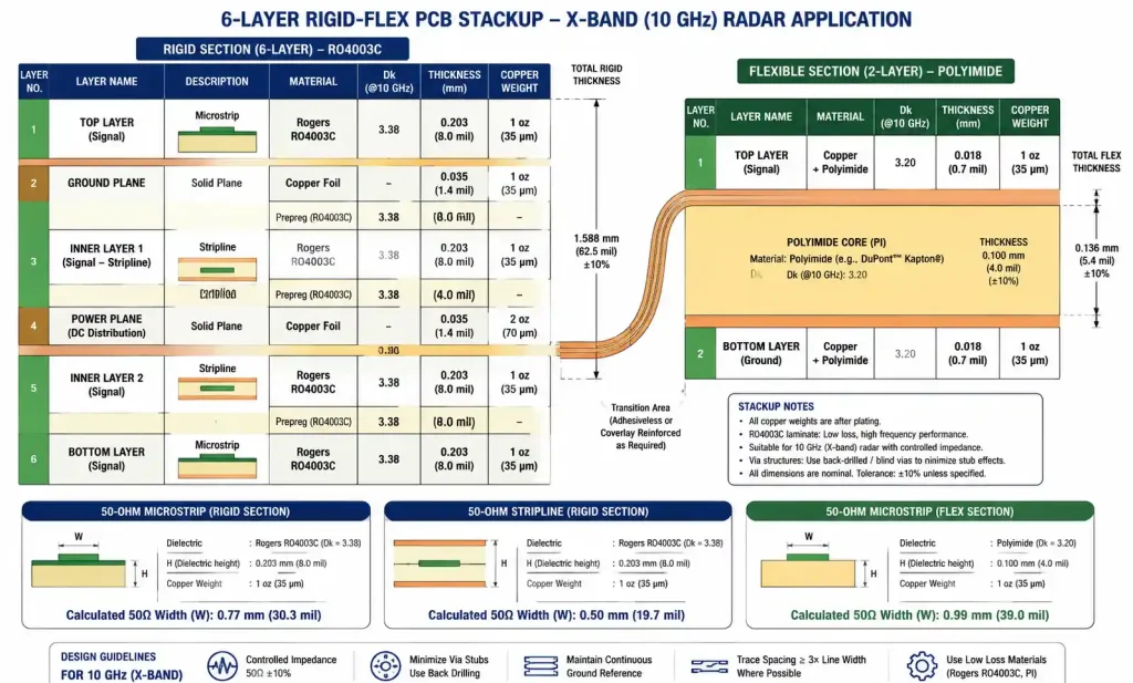
Radar systems operating in X-band (8–12 GHz), Ku-band (12–18 GHz), or Ka-band (26–40 GHz) require low-loss materials to maintain signal integrity over the transmission path. The rigid sections of aerospace rigid-flex PCBs for radar typically use high-frequency laminates such as Rogers RO4003C or Isola Astra MT77, while the flexible sections use low-loss polyimide films (e.g., DuPont Pyralux AP).
Material Property Comparison Table
| Material Property | Standard FR4 | Rogers RO4003C | Isola Astra MT77 | Polyimide Flex (Pyralux AP) |
|---|---|---|---|---|
| Dielectric constant (Dk) at 10 GHz | 4.2–4.6 (unstable) | 3.38 ± 0.05 | 3.00 ± 0.05 | 3.4 ± 0.1 |
| Dissipation factor (Df) at 10 GHz | 0.020 | 0.0027 | 0.0021 | 0.0035 |
| Thermal coefficient of Dk (ppm/°C) | >200 | 40 | 30 | 150 |
| Glass transition temp (Tg) | 130–150°C | >280°C (no Tg) | >200°C | 360°C |
| CTE (Z-axis, ppm/°C) | 14–17 | 46 | 40 | 20 (in-plane) |
| Suitable for frequencies > 10 GHz? | No | Yes | Yes | Yes (limited to flex) |
| Typical application | General electronics | Radar, phased arrays | Millimeter wave | Flex interconnect |
Key insight: Standard FR4 is unsuitable for radar frequencies above 2 GHz due to high dissipation factor (Df = 0.020 typical) and unstable dielectric constant over temperature. High-frequency laminates maintain Df below 0.010 and provide stable Dk across the -55°C to +125°C temperature range required for aerospace applications.
Stackup Design Strategy
For a typical 6-layer rigid-flex radar board:
Rigid Section Stackup (RF signal layers):
- Signal (microstrip) – Rogers RO4003C
- Ground – Rogers RO4003C
- Signal (stripline) – Rogers RO4003C + FR4 prepreg
- Power – FR4 core
- Signal (stripline) – Rogers RO4003C
- Ground – Rogers RO4003C
Flexible Section Stackup (2 layers):
- Coverlay – Polyimide (1 mil)
- Signal – 0.5 oz rolled copper
- Polyimide core (2 mil)
- Signal – 0.5 oz rolled copper
- Coverlay – Polyimide (1 mil)
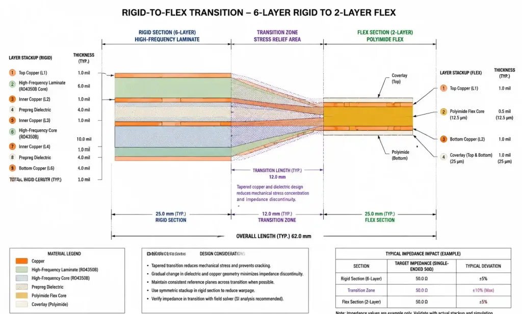
Critical design rule: The rigid-to-flex transition must occur in a low-impedance area or be designed with impedance-matching tapers. Use a short taper (0.05–0.10 inch length) to smoothly transition between trace widths in rigid and flex sections to account for different dielectric constants.
Thermal Management
Active radar modules generate significant heat. The rigid-flex design must provide thermal paths from high-power RF components (power amplifiers, LNAs) to heat sinks or cold plates. Options include:
- Metal-core sections: Integrate aluminum or copper cores into rigid areas
- Thermal vias: Connect hot components to metal core or ground planes
- Thermal pads: Use thermally conductive interface materials
Warning: Flexible sections must be kept away from high-temperature zones. Polyimide begins to degrade above 250°C during soldering, and operating temperatures above 150°C reduce flex cycle life significantly.
Mechanical Reliability Requirements in Aerospace Environments
Aerospace radar systems must survive shock loads up to 100 g, continuous vibration from 10–2000 Hz, and thermal cycling from -55°C to +125°C. Each of these stressors can cause failure in poorly designed rigid-flex assemblies.
Environmental Stress and Design Response Table
| Environmental Stress | Aerospace Requirement | Rigid-Flex Design Response | Failure Mode (Improper Design) |
|---|---|---|---|
| Shock (operational) | 40 g, 11 ms half-sine | Flex section absorbs impact; no rigid mounting near flex | Copper cracking at bend radius |
| Shock (crash survivability) | 100 g | Bend radius ≥ 10× thickness; no components in flex | Delamination at rigid-flex interface |
| Vibration (random) | 0.04 g²/Hz, 20–2000 Hz | Support rigid sections; allow flex to move freely | Solder joint fatigue on rigid sections |
| Thermal cycling | -55°C to +125°C, 500 cycles | CTE-matched materials; stress relief in flex | Barrel cracking in plated vias |
| Flex cycles (dynamic) | 100,000+ cycles minimum | Bend radius ≥ 10× thickness; rolled annealed copper | Copper fracture in flex conductors |
| Altitude (pressure) | Sea level to 70,000 ft | Conformal coating on assemblies | Partial discharge at high altitude |
Rigid-Flex Transition Design Rules
The rigid-flex transition is the most mechanically vulnerable area. Follow these design rules:
- Extend flex material at least 0.10 inch (2.5 mm) beyond the rigid-flex boundary to create a stress relief zone
- Add teardrops to all traces entering the flexible section to prevent copper cracking at the boundary
- Stiffener placement: Stiffeners must end at least 0.05 inch (1.27 mm) before the bend area to avoid creating a hard stop that concentrates stress
- Via placement: Plated through-holes extending from rigid into flex sections create rigid points that resist bending—place transition vias outside dynamic bend areas
- Bend marking: Mark bend areas clearly on silkscreen with bend direction indicators to prevent incorrect assembly
Stiffener Design Guidelines
| Stiffener Material | Typical Thickness | Application | Edge-to-Bend Clearance |
|---|---|---|---|
| Polyimide | 0.005–0.010 inch | Component mounting areas | 0.050 inch minimum |
| FR4 | 0.010–0.030 inch | Connector support | 0.050 inch minimum |
| Stainless steel | 0.005–0.010 inch | High-torque connector areas | 0.050 inch minimum |
Manufacturing Challenges and DFM Considerations
Rigid-flex PCB manufacturing combines the processes for rigid multilayer boards and flexible circuits, creating unique DFM challenges. For aerospace radar applications requiring IPC-6013 Class 3 quality, the manufacturing tolerances are tighter and inspection requirements more stringent than commercial electronics.
DFM Consideration Table
| DFM Consideration | Standard Requirement | Aerospace Radar Requirement | Design Rule Impact |
|---|---|---|---|
| Minimum trace/space in flex | 3/3 mils | 4/4 mils (Class 3) | Conservative routing for reliability |
| Annular ring (IPC Class 3) | 4 mils minimum | 5 mils minimum | Larger pad sizes, lower routing density |
| Rigid-flex registration tolerance | ±5 mils | ±3 mils | Critical for RF impedance matching |
| Impedance tolerance | ±10% | ±5% or ±7% | Requires impedance test on every panel |
| Minimum bend radius marking | Recommended | Mandatory, on both sides | Must be clearly visible during assembly |
| Copper weight in flex | 0.5–1 oz | 0.5 oz (18 μm) preferred | Better flexibility, longer bend life |
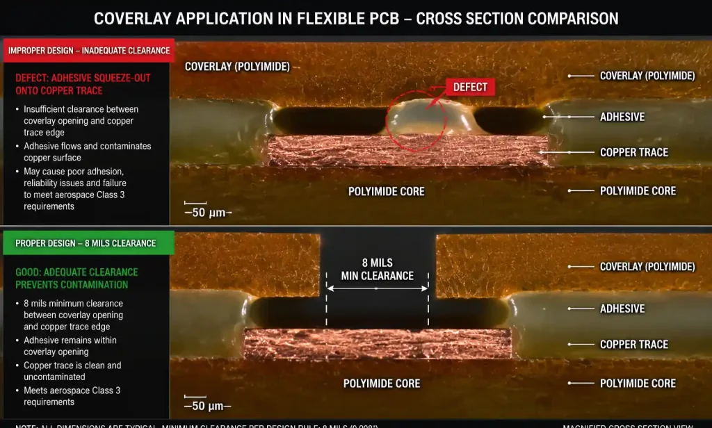
| Coverlay to trace clearance | 5 mils | 8 mils | Prevents coverlay adhesive squeeze-out |
| Stiffener edge to bend | 0.020 inch | 0.050 inch | Adequate stress relief zone |
Critical Manufacturing Processes
Rigid-flex transition lamination:
The flexible layers must align precisely with rigid layers during lamination, with registration tolerance of ±3 mils or better for fine-pitch RF designs. Misalignment at the transition causes impedance discontinuities that degrade radar signal quality.
Impedance control:
Achieving controlled impedance across rigid-flex transitions requires precise control of dielectric thickness during lamination. The flexible polyimide and coverlay materials have different flow characteristics than rigid prepreg, making thickness control more difficult. For 50-ohm microstrip traces, a 10% variation in dielectric thickness causes approximately 5% impedance shift—acceptable for some radar designs but not for precision phase-controlled arrays.
Coverlay application:
Coverlay (adhesive-backed polyimide film) protects flex circuit traces. During lamination, adhesive can flow and squeeze out onto traces or into via holes if clearances are inadequate. For aerospace radar boards, a minimum 8 mils clearance between coverlay edge and conductor is recommended.
Inspection and Testing Requirements
| Test/Inspection | Method | Frequency | Acceptance Criteria |
|---|---|---|---|
| Impedance verification | TDR (Time Domain Reflectometry) | Every panel (test coupons) | ±5% or ±7% per design |
| Layer alignment | X-ray inspection | First article + random | ±3 mils registration |
| Via integrity | Micro-sectioning | First article | IPC Class 3 acceptance |
| Thermal cycling | -55°C to +125°C, 500 cycles | Qualification (first article) | No cracks, no opens |
| Vibration testing | 20–2000 Hz, 0.04 g²/Hz | Qualification (first article) | No mechanical failure |
Lead time planning: Aerospace radar programs typically require first article inspection (FAI) including cross-sectional analysis, impedance testing of all net classes, thermal cycling qualification, and vibration testing. These qualification requirements add 4–6 weeks to first production delivery.
Performance Comparison: Rigid-Flex vs Traditional Cable-Connected Assemblies
Before rigid-flex technology matured, aerospace radar systems used rigid PCBs interconnected with semi-rigid coaxial cables or flexible cable assemblies. While this approach allows easier rework and repair, it introduces reliability and performance limitations that are unacceptable in modern radar systems.
Performance Comparison Table
| Performance Parameter | Cable-Connected Assembly | Rigid-Flex PCB Assembly | Impact on Radar Performance |
|---|---|---|---|
| Insertion loss at 10 GHz | 1.5–2.0 dB (cable + connectors) | 0.5–0.8 dB (microstrip traces) | 1 dB loss = 20% range reduction |
| Phase stability over temperature | ±10° typical (cable expansion) | ±3° (stable PCB materials) | Critical for phased array beam pointing |
| Return loss at transitions | -15 dB (connector interface) | -25 dB (continuous impedance) | Reduced ghost targets, better sensitivity |
| MTBF (vibration environment) | 10,000 hours (connector wear) | 50,000 hours (no wear-out mechanism) | Higher operational availability |
| System weight (64-channel array) | 2.5 kg (cables + connectors) | 1.2 kg (rigid-flex only) | Critical for aircraft/missile systems |
| Assembly time | 40–60 hours (manual cable installation) | 8–12 hours (automated assembly) | Lower manufacturing cost |
| Repair/rework capability | Excellent (replace cables) | Difficult (board replacement) | Trade-off for reliability |
Key Engineering Insights
Insertion loss impact: A 1 dB reduction in insertion loss translates to approximately 20% increase in radar range. For a 64-element phased array, eliminating 128 connectors reduces insertion loss by 40–60 dB cumulative across all channels—a dramatic improvement in system sensitivity.
Phase stability: Coaxial cables expand and contract with temperature, changing electrical length and introducing phase error. Rigid-flex PCBs with temperature-stable dielectrics maintain phase to within ±3° over the -55°C to +125°C aerospace temperature range, compared to ±10° or worse for cable assemblies.
Weight savings: In phased array antennas, cable assembly weight often exceeds PCB weight in cable-connected designs. Rigid-flex eliminates 80–90% of this cable mass—directly translating to increased payload capacity or extended flight range.
Repairability trade-off: A damaged cable can be replaced in minutes; a damaged rigid-flex board typically requires board-level replacement. For aerospace applications, this trade-off favors rigid-flex because in-flight repair is not possible, and the improved reliability reduces failure likelihood.
FAQ
What IPC standard applies to rigid-flex PCBs for aerospace radar applications?
IPC-6013 is the performance specification for rigid-flex PCBs. For aerospace applications, Class 3 is typically required, mandating tighter tolerances on annular ring (5 mils minimum), layer registration (±3 mils), and impedance control (±7% typical). The design must also meet IPC-2223 design guidelines for rigid-flex boards.
Can Rogers high-frequency materials be used in the rigid sections of a rigid-flex board?
Yes. Rogers RO4000 series materials are commonly used in the rigid sections of aerospace radar rigid-flex boards. The key is ensuring thermal expansion compatibility between the Rogers material and the polyimide flex layers during thermal cycling.
What is the typical minimum bend radius for a 2-layer flex section in a radar application?
For dynamic bending (repeated flex cycles): 10× total thickness. For a 2-layer flex with 2 mil polyimide core and 1 mil coverlay each side (total thickness 4 mils): minimum dynamic bend radius = 0.040 inch (1.0 mm) . For static/one-time installation: 6× thickness = 0.024 inch (0.6 mm).
How do I maintain 50-ohm impedance across the rigid-flex transition?
Match trace widths in both rigid and flex sections to account for different dielectric constants using a field solver. Use a short taper (0.05–0.10 inch length) at the transition. Avoid placing vias at the transition; use stripline-to-microstrip transitions on the rigid side.
What causes copper cracking in flexible sections?
Copper cracking occurs when: (1) bend radius is too tight, (2) vias or plating stubs create stress concentration points in the bend area, or (3) copper is too thick. Prevention: use rolled annealed copper (not electrodeposited), maintain 10× thickness bend radius, avoid vias/components in bend areas, and use 0.5 oz copper (not 1 oz) for critical flexibility.
Is impedance testing required for every production board?
For aerospace radar applications under AS9100 quality systems, yes. Controlled impedance is a key characteristic requiring 100% testing or test coupon verification on every manufacturing panel. TDR testing is performed on designated test coupons; results must be documented and provided with the board shipment.
Can components be mounted on flexible sections?
Only if a stiffener is bonded underneath the component area. The stiffener (polyimide or FR4) provides a rigid platform and prevents flexing of solder joints. The stiffener must end at least 0.05 inch before any bend area. For radar applications, keep active RF components on rigid sections.
What is the typical lead time for aerospace-qualified rigid-flex PCBs?
6–8 weeks for first article production including qualification testing; 4–6 weeks for repeat production. If material qualification or FAI with cross-sectioning and thermal cycling is required, add another 2–4 weeks.
Decision Framework: When to Choose Rigid-Flex vs Cable Assemblies
Use this decision matrix to determine whether rigid-flex or cable-connected assembly is right for your aerospace radar application:
| Consideration | Choose Rigid-Flex | Choose Cable Assembly |
|---|---|---|
| Operating frequency | > 2 GHz (RF/microwave) | < 2 GHz or DC-only |
| Vibration environment | High (aircraft, missile) | Low (ground-based, lab) |
| Weight constraints | Critical (airborne, space) | Less critical (ground, shipboard) |
| Phase stability requirement | ±5° or tighter | ±10° or looser |
| Production volume | Medium-high (automated assembly) | Low (manual cable installation) |
| Repair requirements | Board-level replacement acceptable | Field-replaceable cables required |
| Signal count | High (64+ channels) | Low (<16 channels) |
| MTBF requirement | > 50,000 hours | < 20,000 hours acceptable |
Rule of thumb: If your radar system operates above 2 GHz, has more than 16 RF channels, and is installed in an aircraft, missile, or satellite—rigid-flex is the mandatory choice.
Conclusion and Next Steps
Rigid-flex PCB technology is not optional for modern aerospace radar systems—it is a requirement driven by the need for high-frequency performance, mechanical reliability, and weight reduction. The elimination of cable assemblies and connectors improves radar sensitivity by reducing insertion loss, improves reliability by removing mechanical failure points, and reduces system weight by 20–35% compared to cable-connected alternatives.
Key Design Priorities
- Material selection: High-frequency laminates with stable Dk and low Df (Rogers RO4003C, Isola Astra MT77) for rigid sections; 2-layer polyimide flex with 0.5 oz rolled copper
- Bend radius: 10× total thickness for dynamic bending; 6× for static
- Rigid-flex transitions: Impedance matching + stress relief zone (0.10 inch min extension)
- IPC-6013 Class 3: Full impedance testing, X-ray inspection, and qualification
- Lead time planning: 6–8 weeks for first article; add 2–4 weeks for FAI qualification
Immediate Action Items
- [ ] Verify your operating frequency and impedance requirements (50 Ω ±5% or tighter?)
- [ ] Calculate flex section bend radius based on your stackup thickness
- [ ] Review material selection: Rogers/Isola for rigid, polyimide for flex
- [ ] Confirm IPC Class 3 requirements with your PCB manufacturer
- [ ] Plan qualification testing timeline (thermal cycling, vibration, impedance)
Need Expert DFM Review?
Our CAM engineering team has 15+ years of experience with IPC-6013 Class 3 aerospace PCBs and provides free design analysis before fabrication—including rigid-flex transition impedance verification, bend radius validation, and stackup optimization for radar frequencies.