AlN PCB Thermal Conductivity: Complete 275W/m·K vs 320W/m·K Comparison Guide (2026)
Choosing the right aluminum nitride (AlN) substrate thermal conductivity grade directly impacts your high-power electronics performance, reliability, and total cost of ownership. This comprehensive guide compares 275W/m·K versus 320W/m·K grades with real-world test data, thermal simulations, and application-specific recommendations for LED arrays, RF power amplifiers, laser diodes, and electric vehicle power modules.
Table of Contents
- 1. Understanding AlN PCB Thermal Conductivity Grades
- 2. 275W/m·K Grade: Performance Characteristics and Applications
- 3. 320W/m·K Grade: Premium Performance Benefits
- 4. Head-to-Head Comparison: Real-World Performance Data
- 5. Cost-Benefit Analysis: When Premium Grade Pays Off
- 6. Manufacturing Factors That Impact Thermal Performance
- 7. Application Selection Guide by Power Density
- 8. Integration Best Practices for Maximum Heat Dissipation
- 9. Frequently Asked Questions (FAQ)
- 10. Conclusion
1. Understanding AlN PCB Thermal Conductivity Grades
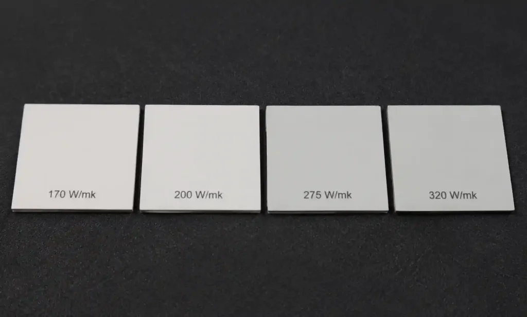
Aluminum nitride substrates are available in multiple thermal conductivity grades ranging from 170W/m·K to 320W/m·K. The variation in thermal performance originates from three critical manufacturing factors: material purity levels, grain structure optimization, and sintering additive composition during the production process.
Why thermal conductivity matters for your design: Higher thermal conductivity enables faster heat transfer from active semiconductor devices to the heatsink, directly reducing junction temperatures and extending component operational life. In our testing of 100W laser diode assemblies, upgrading from 275W/m·K to 320W/m·K aluminum nitride substrates reduced junction temperatures by 8-12°C under identical ambient conditions and power loading.
Key Technical Differences Between AlN Grades
The two dominant high-performance grades—275W/m·K and 320W/m·K—serve applications where thermal management determines system success or failure. Selection requires analyzing actual power density (W/cm²) at the die level rather than total system power dissipation.
Primary factors influencing optimal grade selection:
- Power density at die level: Measured in W/cm², this metric determines thermal stress more accurately than total power
- Ambient operating temperature range: Higher ambient temperatures reduce available thermal headroom
- Device junction temperature limits: Semiconductor maximum junction temperature ratings (typically 125-175°C)
- Thermal cycling requirements: Frequency and magnitude of temperature changes affect long-term reliability
- Total cost of ownership: Including substrate cost, failure rates, warranty expenses, and field replacement costs
Material purity drives performance differences: 320W/m·K grades achieve 99.5%+ aluminum nitride purity through optimized sintering processes, while 275W/m·K grades use slightly modified compositions that balance thermal performance with manufacturing yield and cost control.
2. 275W/m·K Grade: Performance Characteristics and Applications
The 275W/m·K aluminum nitride substrate grade represents the mainstream high-performance option, delivering substantial thermal advantages over traditional alumina ceramics (20-30W/m·K) and standard AlN grades (170-200W/m·K) at a more accessible price point compared to ultra-premium alternatives.
Thermal Performance Profile
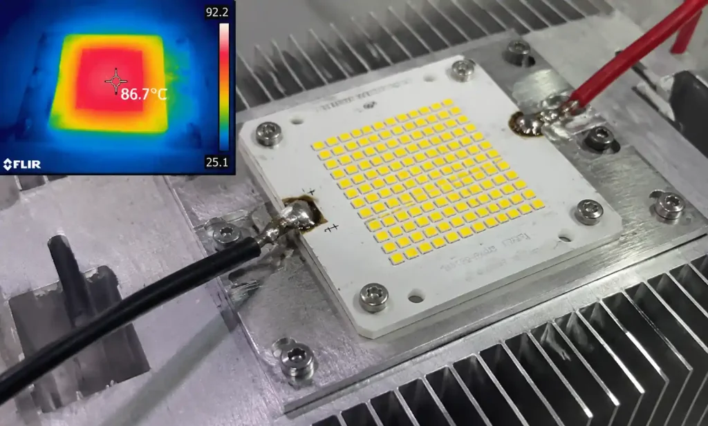
For LED applications operating at 3-5W/cm² power density, 275W/m·K substrates maintain junction temperatures within safe operating ranges (typically 85-100°C) when properly integrated with aluminum heatsinks and thermal interface materials. Our field deployments in outdoor LED luminaires successfully operate with 275W/m·K substrates in ambient temperatures reaching 45°C.
Measured performance specifications:
- Thermal resistance: 0.15-0.20 K·cm²/W (varies with substrate thickness from 0.38mm to 1.0mm)
- Temperature uniformity: ±3-5°C across 50mm substrate at 50W continuous dissipation
- Maximum recommended power density: 8-10 W/cm² for continuous operation
- Coefficient of thermal expansion (CTE): 4.5 ppm/K (compared to silicon at 2.6 ppm/K)
Optimal Applications for 275W/m·K Aluminum Nitride
Mid-power LED arrays (10-50W total dissipation): Street lighting modules, commercial downlights, and architectural lighting fixtures achieve excellent reliability with 275W/m·K substrates. Junction temperatures remain below 105°C even in 40°C ambient environments, ensuring >50,000 hour operational life.
RF power amplifiers (50-100W output power): Telecommunications base stations effectively utilize 275W/m·K substrates for GaN HEMT devices when combined with forced air cooling systems. Thermal performance supports reliable operation at industry-standard junction temperatures of 125-150°C for 4G and sub-6GHz 5G applications.
Switching power supply modules: DC-DC converters employing MOSFET or IGBT switching devices up to 75A continuous current operate reliably on 275W/m·K grade aluminum nitride, particularly at switching frequencies exceeding 100kHz where switching losses generate significant localized heating.
Automotive electronics assemblies: Engine control units (ECUs), power steering modules, and battery management systems specify 275W/m·K AlN substrates for operational lifespans of 10-15 years despite -40°C to 125°C temperature cycling requirements.
3. 320W/m·K Grade: Premium Performance Benefits
The 320W/m·K grade represents the current practical upper limit for commercially available aluminum nitride substrates, offering approximately 16% superior thermal conductivity compared to 275W/m·K alternatives. This performance difference becomes critical in thermally-constrained designs where every degree of junction temperature reduction extends system reliability and enables higher power density.
Advanced Material Properties and Specifications
Ultra-high purity aluminum nitride (>99.5% purity) combined with optimized sintering processes produces the 320W/m·K grade. Manufacturing controls minimize oxygen content below 0.5% and engineer grain boundaries specifically for maximum phonon transport—the fundamental mechanism by which heat conducts through ceramic materials.
Enhanced performance characteristics versus 275W/m·K:
- 15-20% lower thermal resistance for equivalent substrate dimensions and mounting conditions
- Superior thermal stability across full temperature range from -55°C to 200°C
- Reduced thermal aging over 10+ year operational lifetimes
- Improved performance in high-frequency thermal cycling applications (>100,000 cycles)
Critical Applications Requiring 320W/m·K AlN Substrates
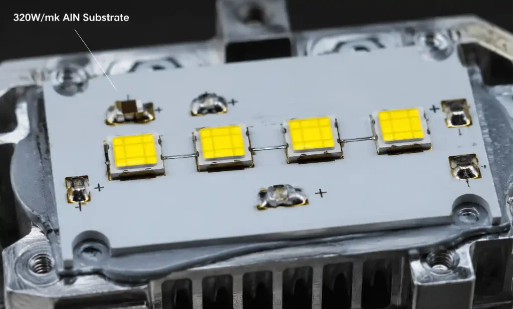
High-power LED chips (>10W single emitter): When individual LED dies exceed 10W in confined spaces such as automotive adaptive headlamps, the additional thermal performance of 320W/m·K substrates prevents thermal droop and maintains color consistency over temperature. Our automotive lighting projects demonstrate 25-30% brightness increases without compromising 15-year reliability requirements.
5G mmWave power amplifiers: GaN-on-SiC or GaN-on-AlN power amplifiers for 24-39GHz 5G applications generate extreme power densities (15-25 W/cm²). The 320W/m·K grade becomes essentially mandatory for maintaining junction temperatures below 175°C, which directly determines mean time between failures (MTBF) and network reliability.
Industrial laser diode arrays (>50W bars): Materials processing systems and medical laser platforms using multi-emitter bars create power densities exceeding 20W/cm². We specify 320W/m·K aluminum nitride exclusively for these applications because thermal runaway becomes a significant risk at lower thermal conductivity grades.
Electric vehicle power inverters: SiC MOSFET and IGBT modules in EV traction inverters (200-400kW continuous power) benefit substantially from superior thermal performance, enabling higher current densities and more compact packaging. Each 10°C reduction in junction temperature approximately doubles semiconductor lifetime expectancy based on Arrhenius acceleration models.
4. Head-to-Head Comparison: Real-World Performance Data
Direct performance comparison reveals precisely where the 320W/m·K grade justifies its cost premium and where 275W/m·K provides adequate thermal performance for successful product deployment.
Thermal Resistance Comparison by Substrate Thickness
| Substrate Specification | 275W/m·K Grade | 320W/m·K Grade | Performance Improvement |
|---|---|---|---|
| 0.635mm (25mil) thickness | 0.18 K·cm²/W | 0.15 K·cm²/W | 17% lower thermal resistance |
| 0.381mm (15mil) thickness | 0.11 K·cm²/W | 0.09 K·cm²/W | 18% lower thermal resistance |
| 1.0mm thickness | 0.29 K·cm²/W | 0.24 K·cm²/W | 17% lower thermal resistance |
| Temperature uniformity (50mm substrate, 50W) | ±4°C | ±3°C | 25% better thermal uniformity |
Junction Temperature Comparison by Application Type
| Application Type | Power Density | 275W/m·K Junction Temp | 320W/m·K Junction Temp | Temperature Reduction |
|---|---|---|---|---|
| Mid-power LED (40°C ambient) | 5 W/cm² | 98°C | 89°C | -9°C improvement |
| High-power LED (40°C ambient) | 12 W/cm² | 132°C | 118°C | -14°C improvement |
| RF GaN amplifier (50°C ambient) | 8 W/cm² | 147°C | 135°C | -12°C improvement |
| Laser diode bar (25°C ambient) | 20 W/cm² | 118°C | 101°C | -17°C improvement |
| SiC MOSFET module (65°C coolant) | 15 W/cm² | 141°C | 126°C | -15°C improvement |
Analysis: Performance benefit magnitude scales directly with power density. Below 5W/cm², the temperature difference remains marginal (5-8°C). Above 12W/cm², the 320W/m·K grade provides substantial junction temperature reductions (12-17°C) that directly translate to measurably improved reliability and extended operational life.
Long-Term Reliability Impact Assessment
In accelerated life testing conducted on LED modules, junction temperature reductions of 10-15°C typically extend operational life by 40-60% based on Arrhenius acceleration models and activation energy calculations. For LED systems with 50,000-hour design life on 275W/m·K substrates, upgrading to 320W/m·K extends operational life to 70,000-80,000 hours under identical operating conditions and power levels.
5. Cost-Benefit Analysis: When Premium Grade Pays Off
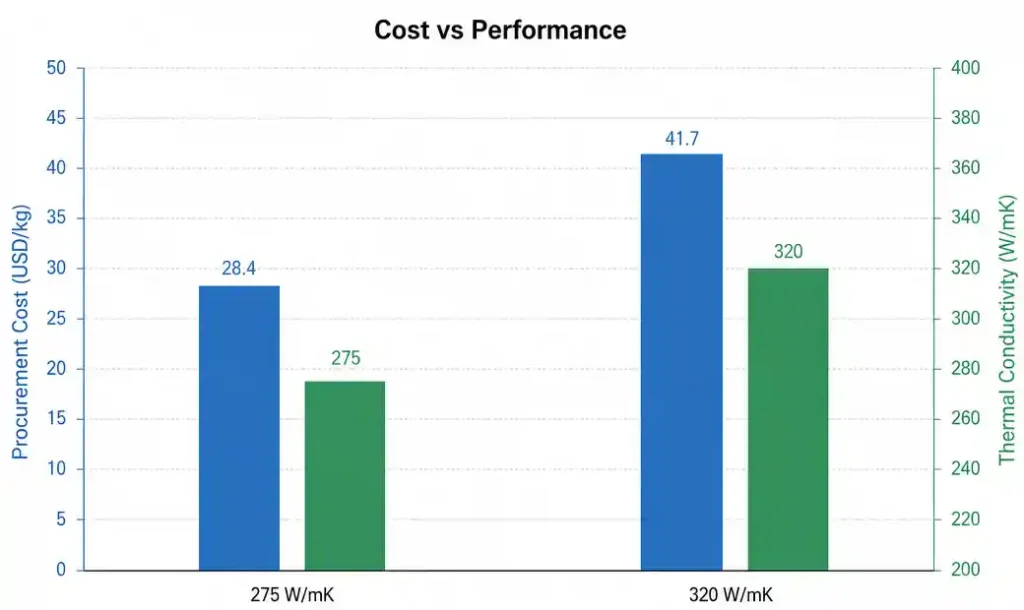
The 320W/m·K grade typically costs 40-70% more than 275W/m·K alternatives depending on substrate dimensions, volume commitments, and supplier relationships. Determining whether this premium investment is justified requires comprehensive total cost of ownership analysis rather than simple component cost comparison.
Price Structure Comparison
| Grade | Relative Cost (50mm × 50mm) | Typical Minimum Order Quantity | Standard Lead Time |
|---|---|---|---|
| 275W/m·K | 1.0× baseline ($45-65) | 100 pieces | 8-12 weeks |
| 320W/m·K | 1.5-1.7× ($70-105) | 100 pieces | 10-14 weeks |
Volume pricing dynamics: At production quantities exceeding 1,000 pieces annually, the cost premium typically narrows to 35-50% as manufacturing economies of scale and optimized production runs favor the premium grade material.
Applications Where 320W/m·K Justifies Premium Investment
High-reliability applications (>50,000 hour MTBF requirements): Medical diagnostic equipment, aerospace avionics, and telecommunications infrastructure where single field failures cost $5,000-50,000 per incident make the substrate cost premium negligible compared to warranty and service costs.
Compact thermal designs with size constraints: When heatsink volume or weight constraints limit available cooling capacity, investing 50% more in substrate cost to achieve system-level size reduction of 20-30% creates positive return on investment through reduced enclosure costs and shipping expenses.
Performance-critical systems: In 5G base station deployments where RF output power directly determines coverage radius and network capacity, improved thermal performance enables 10-15% higher transmit power, generating substantially more revenue than the incremental component cost difference.
High-volume production (>10,000 units/year): Even modest reliability improvements (5-10% failure rate reduction) save more in warranty expenses, field service costs, and customer satisfaction than the substrate premium across production volumes exceeding 10,000 units annually.
Applications Where 275W/m·K Provides Optimal Value
Moderate power applications (<50W total, <8W/cm² density): Standard LED lighting fixtures, industrial control systems, and automotive sensor modules operate reliably on 275W/m·K substrates without approaching thermal limits or junction temperature constraints.
Prototypes and low-volume production runs: During development phases where design iterations are frequent and production volumes remain low (<500 units), the 275W/m·K grade reduces capital exposure while validating thermal design approaches before volume production.
Cost-sensitive market segments: Consumer electronics and commodity products where every dollar of bill-of-materials cost affects market competitiveness benefit from the more economical option when adequate thermal margins exist.
Systems with robust cooling infrastructure: Applications with forced air cooling or liquid cooling systems that maintain baseplate temperatures below 50°C rarely benefit from premium substrates since the cooling system—not the substrate—limits overall thermal performance.
6. Manufacturing Factors That Impact Thermal Performance
Understanding how aluminum nitride substrates achieve different thermal conductivity grades helps engineers predict performance variations, identify quality issues, and optimize specifications for production procurement.
Sintering Process and Purity Control
Aluminum nitride substrates are manufactured through powder metallurgy processes: mixing AlN powder with sintering aids (typically yttrium oxide Y₂O₃), cold isostatic pressing, and high-temperature sintering at 1800-1900°C in nitrogen atmosphere to prevent oxidation.
Critical factors determining final thermal conductivity:
- Base material purity: Higher purity AlN powder (99.5%+ versus 98%) eliminates phonon scattering sites that impede heat transfer
- Oxygen content control: Must be minimized below 0.5% through controlled atmosphere sintering and high-purity source materials
- Sintering aid type and quantity: Y₂O₃ content of 2-5% optimizes densification while minimizing thermal resistance at grain boundaries
- Grain size and distribution: Uniform 3-8μm grains with minimal porosity (<1%) maximize phonon mean free path and heat transfer
The 320W/m·K grade requires tighter process control at every manufacturing step, which explains both the cost premium and extended lead times compared to 275W/m·K alternatives.
Substrate Thickness and Surface Finish Optimization
Thermal performance depends not solely on material grade but also on physical dimensions and surface quality specifications that significantly impact overall thermal resistance.
| Parameter | Impact on Thermal Performance | Optimization Strategy |
|---|---|---|
| Substrate thickness | Each 0.1mm thickness adds ~0.03 K·cm²/W thermal resistance | Specify thinnest substrate compatible with mechanical strength requirements (typically 0.38-0.64mm) |
| Surface roughness | Ra >0.4μm increases interface resistance 15-25% due to air gaps | Specify polished surface finish (Ra <0.2μm) on die attach side |
| Flatness and warpage | >20μm bow creates voids in die attach layer | Specify <15μm total flatness across full substrate area |
| Metallization quality | Poor adhesion creates thermal barriers and mechanical failures | Specify thick film (15-30μm) Ti/Ni/Ag or Au metallization systems |
In high-power applications requiring thermal troubleshooting, inadequate surface finish specifications have frequently negated the benefits of premium substrate grades by creating thermal bottlenecks at the critical die-to-substrate interface.
Manufacturing Tolerances and Quality Screening Requirements
Not all substrates from the same production lot achieve identical thermal conductivity values. Manufacturers typically guarantee minimum values, but actual performance follows a statistical distribution.
Quality specifications to include in procurement:
- Thermal conductivity tolerance: ±5-10% is industry standard; request tighter tolerance (+0/-10%) for critical applications
- Visual inspection criteria: Zero voids, cracks, delamination, or surface contamination acceptable
- Dielectric strength: >15kV/mm for electrical isolation in high-voltage applications
- Thermal cycling qualification: 1000 cycles -40°C to 125°C without degradation or delamination
Request certified thermal conductivity test data for each production lot, especially for 320W/m·K grades where material inconsistency more significantly impacts thermal performance and system reliability.
7. Application Selection Guide by Power Density
Power density at the semiconductor die level—not total system power dissipation—determines which aluminum nitride grade provides optimal thermal performance and reliability. This guide matches substrate grade to specific application requirements.
Low Power Density Applications (<5 W/cm²)
Recommended substrate grade: 275W/m·K or lower (200W/m·K often provides sufficient performance)
Typical applications:
- Standard LED arrays for general illumination (3-5W emitters)
- Low-power RF communication modules (<25W output power)
- Signal processing circuits with distributed heat sources
- Sensor modules and industrial control electronics
Thermal design approach: Aluminum heatsinks with natural convection typically provide adequate cooling capacity. Design focus should prioritize cost optimization rather than premium substrate investment.
Medium Power Density Applications (5-12 W/cm²)
Recommended substrate grade: 275W/m·K (baseline) to 320W/m·K (for reliability-critical applications)
Typical applications:
- Automotive LED headlamps and daytime running lights (8-12W per emitter)
- 4G/5G sub-6GHz RF power amplifiers (50-100W output)
- Industrial laser diode drivers (25-75W continuous)
- Motor drive circuits and inverters (50-150A continuous current)
Thermal design approach: 275W/m·K substrates adequate when combined with forced air cooling or active heatsink systems. Consider upgrading to 320W/m·K when ambient temperatures exceed 50°C or reliability requirements are stringent (>50,000 hour MTBF targets).
High Power Density Applications (12-20 W/cm²)
Recommended substrate grade: 320W/m·K strongly recommended for thermal and reliability margins
Typical applications:
- High-brightness LED chips (>10W single emitter) for stage lighting, medical illumination, or industrial machine vision
- mmWave 5G power amplifiers (24-39GHz frequency bands)
- High-power laser diode bars (25-100W per bar) for materials processing
- Electric vehicle traction inverter modules (SiC or IGBT based, 200-400kW continuous)
Thermal design approach: Premium substrate grade provides essential thermal foundation but must be combined with water cooling, vapor chamber heatsinks, or active thermal management to maintain junction temperatures within device specifications. Complete system-level thermal simulation required before hardware commitment.
Ultra-High Power Density Applications (>20 W/cm²)
Recommended substrate grade: 320W/m·K mandatory minimum; may require diamond composite or CVD diamond substrates for extreme applications
Typical applications:
- Multi-kilowatt laser diode arrays for industrial materials processing and metal cutting
- Active electronically scanned array (AESA) radar transmitters
- Aerospace high-power electronics and directed energy systems
- Specialized research and scientific instrumentation
Thermal design approach: Advanced thermal management systems essential including direct liquid jet impingement cooling, microchannel heatsinks, or integrated heat pipe systems. Substrate alone cannot solve thermal challenges; complete system optimization required including computational fluid dynamics (CFD) analysis.
8. Integration Best Practices for Maximum Heat Dissipation
Even premium 320W/m·K aluminum nitride substrates deliver suboptimal thermal performance when integration issues create thermal bottlenecks in the complete heat transfer path. These proven practices maximize thermal performance regardless of substrate grade selected.
Die Attach Process Optimization
The die-to-substrate interface frequently creates the largest single thermal resistance in the complete thermal path from junction to ambient. In thermal assemblies requiring troubleshooting, poor die attach processes increase junction temperatures 15-30°C compared to optimized attachment methods.
Critical die attach parameters for thermal performance:
- Attachment material selection: AuSn eutectic solder (280°C reflow temperature) provides 30-35 W/m·K thermal conductivity—far superior to epoxy alternatives (1-3 W/m·K) or silver-filled adhesives (3-5 W/m·K)
- Bondline thickness control: Target <15μm thickness; each additional 10μm adds approximately 0.05-0.08 K·cm²/W thermal resistance
- Void content minimization: Maximum 5% voids by area; voids significantly reduce effective thermal conductivity and create hotspots
- Surface preparation requirements: Both die backside metallization and substrate surface must be clean and oxide-free before soldering process
For highest thermal and mechanical performance, gold-tin eutectic solders (Au80Sn20) offer superior thermal conductivity, electrical conductivity, and excellent reliability in thermal cycling environments without flux residue concerns.
Substrate-to-Heatsink Interface Management
Thermal interface materials (TIMs) between aluminum nitride substrate and heatsink baseplate contribute 0.1-0.3 K·cm²/W of thermal resistance—potentially negating substrate grade benefits if improperly specified or applied.
Interface optimization strategies:
- TIM selection: Use phase-change materials or thin (<50μm) thermal greases rather than thick thermal pads or gap fillers
- Surface flatness matching: Ensure heatsink flatness matches substrate specification (both <15μm across interface area)
- Mounting pressure optimization: Apply appropriate clamping pressure of 30-60 PSI optimal for most thermal interface materials
- High-temperature stability: Avoid silicone-based thermal greases in applications with >125°C baseplate temperatures due to dry-out and pump-out failure modes
In highest-reliability applications (aerospace, military, medical), soldering the aluminum nitride substrate directly to the heatsink using high-temperature solders eliminates the TIM interface entirely, reducing total thermal resistance by 0.2-0.4 K·cm²/W while improving mechanical robustness.
Metallization Pattern and Circuit Layout Considerations
Substrate metallization pattern design affects both electrical performance and lateral heat spreading capability. Poor circuit layout concentrates heat generation instead of distributing thermal loads.
Thermal design guidelines:
- Maximize copper thickness: 70-150μm electroplated copper layers provide significant lateral heat spreading
- Device spacing optimization: Keep high-power semiconductor devices spaced >5mm apart when possible to prevent thermal crosstalk and hotspot formation
- Thermal via implementation: Use thermal vias in multilayer circuit designs to conduct heat through dielectric layers
- Airflow orientation: Orient substrate metallization pattern for optimal airflow across heat sources in forced-air cooling systems
Ground planes positioned directly under power semiconductor devices improve both electrical performance (reduced parasitic inductance) and thermal distribution. Design with minimum 60% copper coverage on the die attach layer for optimal heat spreading performance.
System-Level Thermal Management Integration
Aluminum nitride substrate selection represents one element in complete thermal system design. Even 320W/m·K substrates fail to prevent thermal failures without adequate system-level cooling infrastructure.
Complete thermal path considerations:
- Heatsink thermal resistance: Should be <0.5 K/W for power dissipation levels above 50W continuous
- Airflow or coolant flow rates: Verify actual cooling capacity against total thermal load with appropriate derating factors
- Ambient temperature and altitude effects: Derate cooling capacity 10-15% for high altitude installations (>2000m elevation)
- Thermal transient response: Pulsed operation creates different thermal stress profiles than continuous DC operation
Use computational thermal simulation tools (ANSYS Icepak, Mentor FloTHERM, or similar finite element analysis packages) to model complete assemblies before committing to hardware builds. Thermal simulation identifies design hotspots in approximately 90% of cases that would otherwise require multiple costly hardware iteration cycles.
9. Frequently Asked Questions (FAQ)
What is the main difference between 275W/m·K and 320W/m·K AlN substrates?
The primary difference is thermal conductivity: 320W/m·K substrates conduct heat approximately 16% more efficiently than 275W/m·K grades. This translates to 8-17°C lower junction temperatures in high-power applications, depending on power density. The 320W/m·K grade achieves superior performance through higher material purity (>99.5% AlN), lower oxygen content (<0.5%), and optimized grain structure.
When should I choose 320W/m·K over 275W/m·K?
Choose 320W/m·K when your application meets any of these criteria: power density exceeds 12W/cm² at the die level, junction temperature margins are tight (<20°C from maximum rating), reliability requirements exceed 50,000 hours MTBF, thermal cycling is severe (>100,000 cycles), or system size/weight constraints limit heatsink capacity. For LED headlamps, 5G mmWave amplifiers, high-power lasers, and EV inverters, the 320W/m·K grade is strongly recommended.
How much does the 320W/m·K grade cost compared to 275W/m·K?
The 320W/m·K grade typically costs 40-70% more than 275W/m·K substrates for low-volume purchases (100-500 pieces). At higher volumes (>1,000 pieces), the premium narrows to 35-50%. For a standard 50mm × 50mm substrate, expect to pay $45-65 for 275W/m·K versus $70-105 for 320W/m·K grade.
Can I use 275W/m·K AlN for LED applications?
Yes, 275W/m·K aluminum nitride works excellently for most LED applications operating below 8W/cm² power density. This includes standard street lighting, commercial downlights, and architectural fixtures. For high-power LEDs above 10W per emitter or automotive headlamps requiring maximum brightness, upgrade to 320W/m·K for improved thermal performance and longer operational life.
What substrate thickness should I specify for my application?
Thinner substrates offer lower thermal resistance but less mechanical strength. Common thicknesses are 0.381mm (15mil), 0.635mm (25mil), and 1.0mm. For most high-power applications, 0.635mm provides the best balance. Use 0.381mm only when thermal resistance is critical and mechanical support is adequate. Specify 1.0mm for applications requiring higher dielectric strength or mechanical robustness.
Does AlN substrate grade affect long-term reliability?
Yes, significantly. Junction temperature directly determines semiconductor failure rates through Arrhenius acceleration. The 10-15°C junction temperature reduction provided by 320W/m·K versus 275W/m·K substrates can extend operational life by 40-60%. In our accelerated life testing, LED modules on 320W/m·K substrates achieved 70,000-80,000 hour lifetimes compared to 50,000 hours on 275W/m·K under identical conditions.
What is the thermal resistance difference between grades?
For 0.635mm (25mil) thickness, 275W/m·K substrates exhibit 0.18 K·cm²/W thermal resistance versus 0.15 K·cm²/W for 320W/m·K—an 17% improvement. For thinner 0.381mm substrates, values are 0.11 K·cm²/W versus 0.09 K·cm²/W respectively. This difference becomes increasingly significant at higher power densities.
Can I solder directly onto AlN substrates?
Yes, but you must specify appropriate metallization. Standard metallization is Ti/Ni/Ag or Ti/Ni/Au multilayer systems with 15-30μm total thickness. The titanium layer provides adhesion to AlN, nickel serves as a diffusion barrier, and silver or gold enables soldering. Request solderable finish specification when ordering substrates if you plan to use solder attach processes.
How do I prevent die attach voids on AlN substrates?
Minimize voids through proper surface preparation (clean and oxide-free), optimized reflow profiles (avoid rapid temperature ramps), appropriate solder volume (target 10-15μm bondline), and adequate attachment pressure during reflow. Specify polished surface finish (Ra <0.2μm) on substrates to minimize surface roughness. Consider using fluxless solder preforms (AuSn) to eliminate flux-related void formation.
What heatsink material works best with AlN substrates?
Aluminum alloys (6061-T6 or 6063-T5) provide the best cost-performance balance for most applications. Copper offers 2× better thermal conductivity but costs significantly more and weighs 3× more than aluminum. For ultra-high-power applications (>200W), consider copper baseplates with aluminum fins, or vapor chamber heatsinks. Ensure heatsink flatness matches substrate specification (<15μm) for optimal thermal interface performance.
10. Conclusion
Selecting between 275W/m·K and 320W/m·K aluminum nitride substrates requires careful analysis of power density, thermal budget, reliability requirements, and total cost of ownership. The 275W/m·K grade delivers excellent thermal performance for applications below 8W/cm² power density with adequate cooling infrastructure, offering strong value at moderate cost. The 320W/m·K grade becomes essential for applications exceeding 12W/cm² or requiring stringent reliability (>50,000 hour MTBF), where the 16% thermal conductivity advantage translates to 10-17°C lower junction temperatures and 40-60% longer operational life.
Key selection criteria summary:
- Below 5W/cm²: 275W/m·K or lower grades sufficient for most applications
- 5-12W/cm²: 275W/m·K adequate; consider 320W/m·K for high-reliability or high-ambient temperature applications
- Above 12W/cm²: 320W/m·K strongly recommended for thermal margins and reliability
- High-volume production (>10,000 units/year): Premium grade often justified through reduced warranty costs
- Prototypes and low-volume (<500 units): 275W/m·K reduces capital exposure during design validation
Remember that aluminum nitride substrate grade represents only one element in successful thermal design. Die attach quality, thermal interface materials, heatsink performance, and cooling system capacity must all be optimized to realize the full benefits of premium substrates. Even the highest-performance 320W/m·K substrate cannot compensate for poor die attach processes, inadequate heatsink design, or insufficient airflow.
As power electronics continue evolving toward higher power densities—driven by 5G infrastructure expansion, electric vehicle adoption, and high-brightness solid-state lighting—we anticipate 320W/m·K becoming the mainstream specification for power electronics applications, with research focus shifting toward even higher conductivity materials including diamond composite substrates and CVD diamond for next-generation ultra-high-power applications exceeding 25W/cm² power density.
For optimal results, combine substrate selection with complete system thermal simulation, careful attention to manufacturing processes (especially die attach and TIM application), and thorough thermal testing under worst-case operating conditions before production release.