Best Conformal Coating for High Humidity Environments
When designing electronics for high-humidity applications, selecting the right conformal coating can mean the difference between a reliable product and a costly field failure. This guide breaks down coating chemistry, moisture resistance data, and application-specific selection criteria to help you make an informed decision for automotive, marine, industrial control, and outdoor electronics.
Table of Contents
- What This Guide Covers
- Why Humidity Matters for PCB Reliability
- Conformal Coating Types and Moisture Resistance Performance
- Critical Selection Parameters for High-Humidity Applications
- Application Process and Thickness Control for Maximum Protection
- Testing and Validation Standards
- Common Failure Modes and How to Avoid Them
- FAQ
- Conclusion: Decision Framework for Your Next Design
1. What This Guide Covers
This guide focuses on conformal coating selection for PCB assemblies that must survive prolonged exposure to high relative humidity (RH) — typically 85% RH or higher — combined with temperature cycling, condensation risk, or salt spray environments. You’ll learn which coating chemistries deliver the best moisture barrier performance, how to specify coating thickness and application methods for different production volumes, and what standards-based testing can validate your design before field deployment.
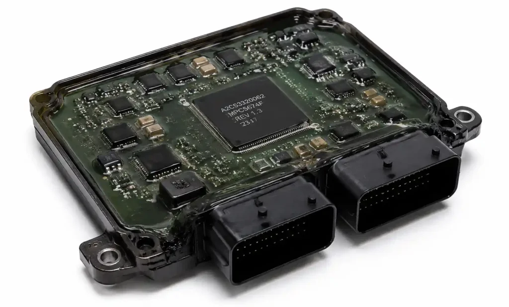
Whether you’re designing automotive ECUs exposed to underhood condensation, industrial sensors for humid process environments, or marine navigation equipment, this guide provides the technical data and engineering judgment needed to select a coating that won’t delaminate, blister, or allow corrosion under the film.
We’ll cover acrylic (AR), silicone (SR), urethane (UR), parylene (XY), and epoxy coatings, focusing on water vapor transmission rate (WVTR), dielectric withstand voltage under humid conditions, salt fog resistance per IPC-HDBK-830, and long-term adhesion after thermal cycling. This guide assumes you’re familiar with PCB assembly processes and need to make a coating choice based on reliability requirements, not marketing claims.
2. Why Humidity Matters for PCB Reliability
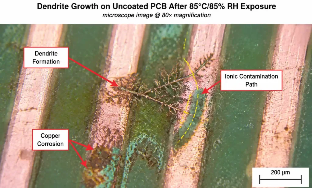
High humidity accelerates electrochemical migration (ECM), dendrite growth between conductors, and corrosion of copper traces, solder joints, and component leads. At 85% RH and 85°C — the standard accelerated life test condition — a thin water film can form on the PCB surface, enabling ionic contamination (flux residues, handling salts, atmospheric pollutants) to conduct current between adjacent traces.
For fine-pitch components (0.4mm pitch BGAs, 01005 passives), even a few angstroms of moisture absorption into the coating can reduce insulation resistance from gigaohms to megaohms or lower, increasing leakage current and noise. In power circuits, this can lead to unexpected bias shifts or latchup. In RF circuits, moisture changes the effective dielectric constant of the coating, shifting impedance and degrading return loss.
Conformal coating acts as a physical barrier to moisture ingress and a chemical barrier to ionic contamination. However, no coating is a perfect hermetic seal. All organic coatings absorb some moisture; the question is how much, how fast, and whether that absorbed moisture can reach the PCB surface in sufficient quantity to enable corrosion or leakage.
The key performance metric is water vapor transmission rate (WVTR), measured in g/m²/day at a given temperature and humidity gradient. Lower WVTR means slower moisture equilibration and better long-term protection. But WVTR alone doesn’t tell the full story — you also need to consider coating adhesion under humidity, thermal expansion mismatch, reworkability, and whether the coating can survive process stresses like reflow repair or in-circuit test.
3. Conformal Coating Types and Moisture Resistance Performance
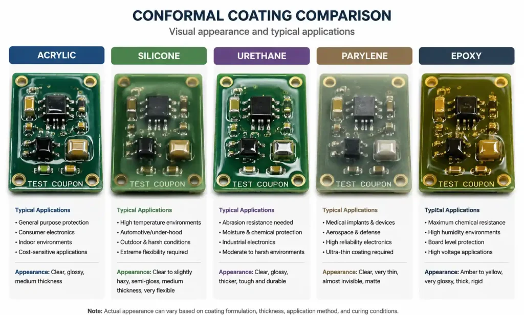
The five most common coating chemistries have very different moisture barrier properties, application requirements, and cost profiles. Here’s a detailed comparison based on published material properties and our CAM engineering experience across thousands of coating runs.
Coating Chemistry Comparison
| Coating Type | WVTR (g/m²/day at 38°C, 90% RH) | Dielectric Strength (V/mil) | Moisture Absorption (% weight) | Salt Fog Resistance (IPC-HDBK-830) | Reworkability | Typical Thickness (mils) |
|---|---|---|---|---|---|---|
| Acrylic (AR) | 15–30 | 1000–1500 | 1.5–3.0 | Moderate (500–1000 hrs) | Excellent (solvent removable) | 1.0–3.0 |
| Silicone (SR) | 50–120 | 500–800 | 0.1–0.5 | Good (1000–2000 hrs) | Poor (requires mechanical removal) | 2.0–5.0 |
| Urethane (UR) | 5–15 | 1500–2500 | 0.5–1.5 | Excellent (2000+ hrs) | Moderate (requires heat + solvent) | 1.0–3.0 |
| Parylene (XY) | 0.5–2.0 | 5000–7000 | <0.1 | Excellent (3000+ hrs) | Very poor (mechanical removal only) | 0.5–2.0 |
| Epoxy | 3–10 | 2000–3000 | 0.3–1.0 | Excellent (2000+ hrs) | Very poor (destructive removal) | 2.0–5.0 |
This table shows measured performance for coatings applied at the manufacturer’s recommended thickness and fully cured per datasheet specifications. WVTR values are for 1-mil coating thickness; thicker coatings proportionally reduce transmission rate but add cost, weight, and thermal resistance.
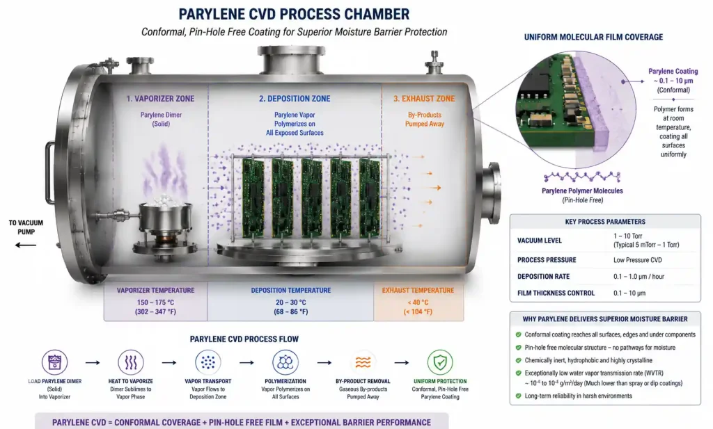
Parylene delivers the best moisture barrier performance by a wide margin — WVTR of 0.5–2.0 g/m²/day is 10–20× better than urethane and 50–100× better than silicone. This is because parylene is deposited as a true molecular film via chemical vapor deposition (CVD), with no pinholes, voids, or solvent inclusions. However, parylene requires specialized batch processing equipment, has long lead times, and cannot be reworked without destroying the board.
Urethane coatings (UR) offer the best balance of moisture resistance, chemical resistance, and mechanical toughness for most high-humidity applications. WVTR of 5–15 g/m²/day is sufficient to protect against condensation and salt spray in automotive, marine, and industrial environments. Urethane has excellent adhesion to FR4, solder mask, and most component bodies, and it can survive thermal cycling from -40°C to +125°C without cracking or delaminating.
Acrylic coatings (AR) have moderate moisture resistance but excellent reworkability, making them suitable for prototypes, low-volume production, or designs that require frequent repair. Acrylics are easy to apply by brush, spray, or selective coating, and they cure at room temperature or with mild heat. However, WVTR of 15–30 g/m²/day means acrylics are not recommended for continuous exposure to 85% RH or higher unless applied at 3–5 mils thickness.
Silicone coatings (SR) have the highest WVTR of any coating type — 50–120 g/m²/day — which makes them unsuitable for high-humidity environments despite their excellent temperature range (-65°C to +200°C) and flexibility. Silicone is best reserved for thermal cycling or mechanical stress applications where moisture is not a primary concern.
4. Critical Selection Parameters for High-Humidity Applications
When evaluating coatings for high-humidity reliability, focus on these engineering parameters rather than generic marketing claims about “waterproofing” or “environmental protection.”
Moisture Barrier Performance
Water vapor transmission rate (WVTR) is the single most important parameter for humidity resistance. For continuous exposure to 85% RH or higher, specify WVTR <15 g/m²/day at 38°C. For outdoor or marine applications with direct water exposure (rain, spray, condensation), specify WVTR <5 g/m²/day. For hermetic-level protection (implantable medical devices, downhole oil & gas sensors), specify WVTR <2 g/m²/day, which typically requires parylene or multi-layer coating systems.
WVTR is inversely proportional to coating thickness — doubling the thickness roughly halves the WVTR, assuming no pinholes or voids. However, thick coatings (>3 mils) increase thermal resistance, add weight, and may crack during thermal cycling due to CTE mismatch with the substrate.
Adhesion Under Humidity
Coating adhesion degrades over time when exposed to moisture, especially if there is residual flux, handling contamination, or inadequate surface preparation. Test adhesion per IPC-TM-650 Method 2.4.28 (cross-hatch tape test) after 1000 hours at 85°C/85% RH. For high-reliability applications, require zero delamination or blistering after this conditioning.
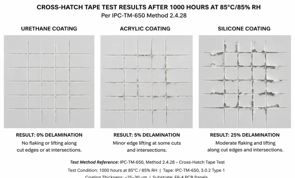
Urethane and parylene have the best adhesion retention under humidity because they form covalent bonds with surface oxides and hydroxyl groups on the PCB. Silicone has weak adhesion by design (to allow flexibility), which can allow moisture ingress at the coating-substrate interface. Acrylic adhesion is moderate and can be improved with a primer or plasma treatment.
Dielectric Withstand Voltage in Humid Conditions
For high-voltage designs (>50V operating voltage), test dielectric strength per IPC-TM-650 Method 2.5.6 after humidity conditioning. Specify a minimum breakdown voltage of 500V for coatings tested at 1-mil thickness after 168 hours at 85°C/85% RH. Moisture absorption reduces dielectric strength by 20–50% compared to dry conditions, so don’t rely on datasheet values measured in ambient lab conditions.
Parylene and urethane maintain the highest dielectric strength under humidity. Silicone has lower dielectric strength but also lower moisture absorption, so its performance degrades less. Acrylic shows the largest degradation under humidity due to its higher moisture absorption (1.5–3.0% by weight).
Chemical Resistance to Flux Residues and Contaminants
No-clean flux residues, ionic contaminants from handling, and atmospheric pollutants (sulfur compounds, chlorides) can concentrate under the coating if not removed during cleaning. These contaminants accelerate ECM and corrosion even with a good coating. For high-humidity applications, always use aqueous cleaning or IPA rinsing before coating, and verify cleanliness per IPC-TM-650 Method 2.3.25 (ionic contamination test).
Urethane and epoxy coatings are most resistant to flux-related degradation. Silicone is permeable to low-molecular-weight contaminants and should not be used over no-clean flux residues. Acrylic can soften or swell when exposed to some flux activators, especially rosin-based fluxes.
Selection Matrix by Application
| Application | Target Environment | Recommended Coating | Typical Thickness | Key Validation Test |
|---|---|---|---|---|
| Automotive ECU (underhood) | 85% RH, -40°C to +125°C, salt spray | Urethane (UR) | 2.0–3.0 mils | IPC-HDBK-830 salt fog 1000 hrs |
| Marine navigation electronics | 95% RH, salt fog, UV exposure | Urethane (UR) or Parylene (XY) | 2.0–4.0 mils | MIL-STD-810 Method 509 (salt fog) |
| Industrial sensor (outdoor) | 90% RH, -20°C to +70°C, dust | Urethane (UR) | 1.5–2.5 mils | IPC-HDBK-830 humidity cycling |
| HVAC control board | 80% RH, condensation risk | Acrylic (AR) or Urethane (UR) | 1.5–2.0 mils | 85/85 test 500 hrs |
| Medical implantable device | Body fluid exposure, 37°C | Parylene (XY) | 1.0–2.0 mils | USP Class VI biocompatibility |
| LED lighting driver (outdoor) | 85% RH, UV, thermal cycling | Urethane (UR) | 2.0–3.0 mils | IPC-HDBK-830 + thermal shock |
This matrix reflects design rules we’ve developed across multiple industries where humidity-related failures drive warranty costs. Note that some applications may require dual-layer coatings (e.g., urethane base + parylene top coat) for extreme environments or mission-critical reliability.
5. Application Process and Thickness Control for Maximum Protection
Even the best coating chemistry will fail if applied incorrectly. Coating thickness uniformity, edge coverage, and void-free application around tall components are critical for moisture barrier performance.
Application Methods Comparison
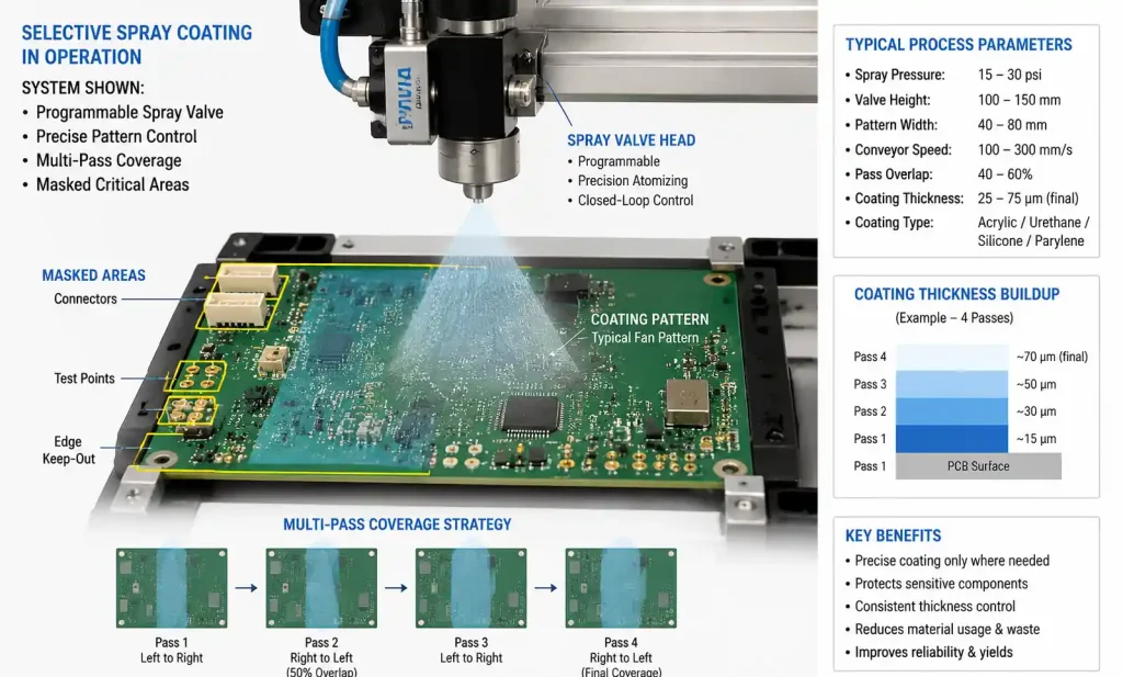
Selective spray coating is the most common method for production volumes above 1000 units/year. A programmable spray valve applies coating in a controlled pattern, avoiding connectors, test points, and keep-out zones. Selective spray delivers 1.5–3.0 mil thickness with ±0.3 mil uniformity, assuming proper viscosity control and multi-pass application. For high-humidity applications, specify at least two spray passes with intermediate cure to avoid pinholes and voids.
Dip coating provides the best edge coverage and penetration around component bodies, but it coats the entire board including connectors and mounting holes. Dip coating is suitable for simple boards with few connectors or boards where masking can be applied before dipping. Thickness uniformity is excellent (±0.2 mils) but harder to control than spray — it depends on withdrawal speed, viscosity, and solids content.
Brush application is only suitable for prototypes, repair, or very low volume (<100 units/year). Brush coating cannot achieve thickness uniformity better than ±1.0 mil, and it’s prone to voids, bubbles, and incomplete coverage around components. For high-humidity applications, brush coating is not recommended unless followed by inspection and touch-up under UV light.
Parylene CVD is a batch process where the board is placed in a vacuum chamber and parylene monomer is vaporized, then polymerizes directly on all exposed surfaces as a molecular film. Parylene provides the most uniform coverage (±0.1 mil) and complete penetration into narrow gaps (down to 0.001″ clearance). However, parylene requires masking of connectors and test points with high-temperature tape or fixtures, and it cannot be applied selectively to specific board areas.
Thickness Measurement and Verification
Specify coating thickness as a range, not a single target value, to allow for production variation. For high-humidity applications, the minimum thickness is more critical than the average — a single pinhole or thin spot can allow moisture ingress and corrosion initiation.
Use a dry film thickness (DFT) gauge with a magnetic probe for non-destructive thickness measurement on flat areas. For measurements around components or in tight spaces, use cross-section microscopy on sample boards from each production lot. Verify thickness at the thinnest expected location (typically the apex of tall components or the center of large flat areas) and confirm it meets the minimum specification.
For urethane and acrylic coatings, specify 1.5–2.5 mils minimum, 2.0–3.5 mils typical. For parylene, specify 0.5–1.0 mils minimum, 1.0–2.0 mils typical. Thicker is not always better — coatings above 5 mils can crack during thermal cycling or trap voids during cure.
Process Control for Maximum Moisture Resistance
Surface preparation is critical. For high-humidity applications, use aqueous cleaning with DI water rinse and forced-air drying at 80–100°C for 30 minutes before coating. Verify surface cleanliness with a contact angle test (water droplet should bead up, not spread) or ionic contamination measurement (<1.56 µg NaCl equiv./cm²).
Plasma treatment (oxygen or argon plasma for 30–60 seconds) significantly improves coating adhesion on solder mask, component bodies, and metal surfaces. Plasma creates surface hydroxyl groups that bond covalently with urethane and parylene coatings. For automotive and marine applications, plasma treatment is strongly recommended before coating.
Cure the coating per the manufacturer’s datasheet — do not under-cure to save cycle time. Under-cured urethane has higher WVTR and weaker adhesion. For two-part urethane coatings, verify pot life and mix ratio are controlled within specification. For UV-cure acrylics, measure UV dose with a radiometer and confirm full cure (no tackiness) before handling.
6. Testing and Validation Standards
For high-humidity applications, specify environmental testing that simulates the actual field exposure conditions, not just generic qualification tests. Here are the most relevant standards and test conditions for conformal coating validation.
IPC-HDBK-830: Guidelines for Design, Selection and Application of Conformal Coatings
This is the primary reference for conformal coating selection, application, and testing. Section 4 covers moisture resistance testing including salt fog (ASTM B117), humidity cycling, and moisture/insulation resistance (MIR) testing per IPC-TM-650 Method 2.6.3.3. For high-humidity applications, specify the following tests as a minimum:
- 85/85 test: 1000 hours at 85°C/85% RH with bias voltage applied (typically 50V DC for logic circuits, higher for power circuits). Measure insulation resistance weekly; require >100 MΩ throughout the test with no degradation trend.
- Salt fog test (ASTM B117): 1000–2000 hours continuous exposure to 5% NaCl fog at 35°C. Inspect for corrosion, delamination, or blistering after test. For marine and automotive applications, this is a critical qualification requirement.
- Thermal cycling with humidity: -40°C to +85°C thermal shock (15-minute dwell, <5-minute transition) combined with 85% RH exposure during the hot phase. 500 cycles minimum. This test reveals coating adhesion failures and CTE mismatch issues that don’t appear in steady-state humidity testing.
MIL-I-46058C (Obsolete but Still Referenced)
Although this military standard has been superseded by performance-based specifications, many legacy designs still reference MIL-I-46058C Type ER (urethane), Type SR (silicone), or Type AR (acrylic). If your customer specification references MIL-I-46058C, verify that the coating supplier can provide a certificate of compliance and that the coating has been tested per the requirements in Table II (moisture and insulation resistance).
UL 746E: Polymeric Materials for Electrical Equipment
For products requiring UL listing, the conformal coating must have a UL 746E yellow card showing the relative thermal index (RTI), flammability rating (typically V-0 or V-1), and comparative tracking index (CTI). For high-humidity applications, verify that the coating’s CTI is ≥175V (Material Group IIIa) to resist tracking and arcing in contaminated humid conditions.
Acceptance Criteria for High-Reliability Designs
| Test | Duration | Pass Criteria | Failure Mode to Watch For |
|---|---|---|---|
| 85°C/85% RH bias test | 1000 hrs | IR >100 MΩ, no ECM | Dendrite growth between fine-pitch traces |
| Salt fog (ASTM B117) | 1000 hrs | No visible corrosion, no blistering | Coating delamination, solder joint corrosion |
| Thermal shock + humidity | 500 cycles | No cracks, no delamination | Coating fracture at component edges |
| Moisture absorption | 168 hrs soak | <2% weight gain | Coating swelling, softening |
| Fungus resistance (MIL-STD-810 Method 508) | 28 days | No fungal growth under coating | Organic contaminant outgassing |
These are minimum qualification tests for automotive Tier 1, aerospace, and marine applications. For consumer or commercial designs, you may be able to reduce test duration or eliminate some tests based on field environment analysis.
7. Common Failure Modes and How to Avoid Them
Even properly selected and applied coatings can fail under high humidity if certain design or process errors are present. Here are the most common failure modes we see in failure analysis, along with root cause and prevention strategies.
Electrochemical Migration (ECM) and Dendrite Growth
ECM occurs when ionic contaminants (flux residues, handling salts, chlorides) create a conductive path between adjacent traces or pads under humid conditions. A small leakage current (even microamps) causes metal ions to migrate from anode to cathode, forming dendritic structures that eventually bridge the gap and cause a short circuit.
Root cause: Inadequate cleaning before coating, insufficient coating thickness, or pinholes in the coating that allow moisture to reach the PCB surface.
Prevention: Aqueous cleaning with DI water rinse before coating. Verify cleanliness <1.56 µg NaCl/cm². Apply coating to minimum 2.0 mils thickness with 100% coverage verification. For fine-pitch BGAs (<0.5mm pitch), consider parylene or dual-layer coating. Design with wider clearances (≥0.3mm) between high-voltage traces and adjacent conductors.
Coating Delamination or Blistering
Delamination occurs when the coating separates from the PCB surface due to weak adhesion, CTE mismatch, or moisture trapped at the interface. Blistering is localized delamination caused by outgassing of absorbed moisture or volatile contaminants during thermal cycling.
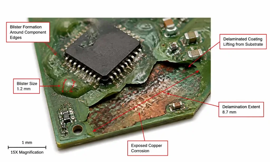
Root cause: Poor surface preparation (oily or contaminated surface), coating applied to a surface that is too hot (>50°C) or too cold (<15°C), insufficient cure time, or excessive coating thickness (>5 mils).
Prevention: Plasma treatment before coating. Verify surface temperature 20–30°C during coating application. Allow fully cured coating to cool slowly (no forced cooling). Limit coating thickness to 3.0 mils maximum for urethane, 2.0 mils for parylene. For large boards (>300mm), use a coating with low CTE mismatch or apply in multiple thin layers.
Pinholes and Voids Around Tall Components
Pinholes are microscopic defects in the coating that allow moisture to reach the PCB surface. Voids are larger uncoated areas, often found in shadowed regions around tall components, between closely spaced parts, or under low-clearance components. Both defects eliminate the moisture barrier effect and allow localized corrosion.
Root cause: Single-pass coating application, incorrect spray pattern or angle, component placement too close together (<5mm spacing), or coating viscosity too high for good flow.
Prevention: Use multi-pass spray coating with 90° orientation change between passes. Adjust spray pattern to ensure coverage under component bodies and between parts. For critical designs, apply a thin primer coat followed by a thicker topcoat. Inspect coating under UV light or with fluorescent tracer to verify 100% coverage. Use X-ray or cross-section microscopy to verify coating penetration under BGAs and QFNs.
Coating Cracking or Crazing After Thermal Cycling
Coating cracks allow moisture ingress and concentrated stress at component edges, leading to solder joint failures or trace fractures. Crazing is a network of fine surface cracks that may not penetrate the full coating thickness but still degrade moisture barrier performance.
Root cause: CTE mismatch between coating and substrate, insufficient coating flexibility, or coating applied too thick (>5 mils).
Prevention: For applications with wide thermal cycling (-40°C to +125°C), select a urethane or silicone coating with low modulus and high elongation (>100%). Limit coating thickness to 3.0 mils. Avoid coating over sharp edges or component corners — use rounded components where possible. If using parylene, limit thickness to 1.5 mils maximum and design with generous fillet radii on component edges.
Moisture Ingress Through Uncoated Connectors or Mounting Holes
Moisture can wick along wire leads, connector pins, or through uncoated mounting holes and then spread laterally under the coating via capillary action. This is a common failure mode in outdoor or marine electronics where connectors are exposed to rain or spray.
Root cause: Connector keep-out areas too large (coating stops too far from the connector body), mounting holes not sealed, or cable entry points not potted.
Prevention: Minimize connector keep-out areas — coating should extend to within 1–2mm of the connector plastic body. Use conformal coating with good wicking resistance (urethane or parylene, not acrylic). Seal mounting holes with non-conductive epoxy or silicone. Pot cable entry points with two-part urethane potting compound. For outdoor applications, add a secondary moisture barrier such as a gasketed enclosure or IP67-rated connector.
8. FAQ
Q: What is the difference between water resistance and moisture resistance for conformal coatings?
Water resistance refers to the coating’s ability to repel liquid water (rain, spray, condensation droplets), typically measured by contact angle or water bead test. Moisture resistance refers to the coating’s ability to block water vapor transmission, measured by WVTR. A coating can have good water resistance (hydrophobic surface) but poor moisture resistance (high WVTR), as is the case with silicone. For high-humidity environments, moisture resistance (low WVTR) is more important than water resistance.
Q: Can I use acrylic conformal coating for outdoor electronics exposed to 90% humidity?
Acrylic coatings have moderate moisture resistance (WVTR 15–30 g/m²/day) and can be used for outdoor electronics if applied to 3–4 mils thickness and combined with good enclosure design. However, for continuous exposure to 90% RH or higher, urethane or parylene coatings are strongly recommended due to their lower WVTR and better long-term adhesion retention under humidity.
Q: How do I calculate the required coating thickness for my humidity environment?
Coating thickness should be selected based on the expected humidity level, temperature, and required service life. As a general rule, for 85% RH continuous exposure, specify 2.0–3.0 mils minimum for urethane, 1.0–2.0 mils for parylene. For intermittent humidity or <80% RH, 1.5–2.0 mils urethane is sufficient. WVTR is inversely proportional to thickness, so doubling thickness roughly halves moisture transmission rate. However, coatings above 5 mils can crack during thermal cycling.
Q: What is the best conformal coating for automotive underhood applications?
Urethane (UR) coatings are the industry standard for automotive underhood electronics because they offer excellent moisture resistance (WVTR 5–15 g/m²/day), chemical resistance to oils and fuels, and thermal cycling performance from -40°C to +125°C. Automotive OEMs typically require IPC-HDBK-830 salt fog testing (1000–2000 hours) and 85/85 testing (1000 hours) for underhood qualification. Parylene is used for critical safety systems (ABS, airbag) but adds significant cost.
Q: Can conformal coating prevent corrosion on PCBs with no-clean flux residues?
No. Conformal coating is not a substitute for proper cleaning. No-clean flux residues contain ionic activators that accelerate ECM and corrosion even under a coating, especially in high-humidity environments. For high-reliability applications, always use aqueous cleaning or IPA rinsing before coating. If no-clean flux must be used, select a low-residue flux with low ionic contamination (<1.0 µg NaCl equiv./cm²) and verify cleanliness before coating.
Q: How do I inspect conformal coating for pinholes and voids?
Use UV inspection with a fluorescent tracer additive in the coating. Under UV light (365nm), the coating will fluoresce brightly, and any pinholes, voids, or thin spots will appear as dark areas. For critical applications, use a low-magnification microscope (10–20×) to inspect around fine-pitch components, under BGAs, and at component edges. For production verification, measure coating thickness with a DFT gauge at multiple locations and verify minimum thickness meets specification.
Q: Can I rework a PCB coated with urethane or parylene?
Urethane can be removed with a combination of heat (120–150°C) and solvent (isopropyl alcohol, acetone, or specialized coating removers). Use a hot air pencil to soften the coating, then wipe with solvent-soaked swabs. Parylene cannot be removed with solvents — it must be mechanically abraded with a fiber brush, micro-blasting, or plasma etching. For designs that require frequent rework, use acrylic coating or leave rework areas uncoated with a keep-out zone.
Q: What is the shelf life of conformal coating materials?
Most conformal coatings have a shelf life of 6–12 months from date of manufacture when stored in sealed containers at room temperature. Two-part urethane coatings have shorter pot life (1–8 hours after mixing depending on formulation). UV-cure acrylics can have shelf life up to 12 months if protected from light. Always verify the expiration date on the coating container and do not use expired materials, as they may have higher viscosity, slower cure time, or reduced adhesion performance.
9. Conclusion: Decision Framework for Your Next Design
Selecting the best conformal coating for high-humidity environments requires balancing moisture barrier performance, application process constraints, reworkability requirements, and cost. Here’s a decision framework based on the technical analysis in this guide:
For automotive, marine, and outdoor industrial applications where continuous exposure to 85% RH or higher is expected, specify two-part urethane (UR) coatings with WVTR <15 g/m²/day, applied to 2.0–3.0 mils minimum thickness. Require IPC-HDBK-830 salt fog testing (1000 hours minimum) and 85/85 bias testing (1000 hours) for qualification.
For mission-critical or implantable medical devices where hermetic-level protection is required, specify parylene (XY) coatings with WVTR <2 g/m²/day. Accept the higher cost and limited reworkability in exchange for superior moisture barrier performance and long-term reliability.
For prototypes, low-volume production, or designs requiring frequent rework, acrylic (AR) coatings provide adequate moisture protection (WVTR 15–30 g/m²/day) with excellent solvent removability. Apply to 2.5–3.5 mils thickness for humidity resistance.
For all high-humidity applications, prioritize surface cleaning before coating — verify ionic contamination <1.56 µg NaCl equiv./cm² — and use plasma treatment to improve adhesion. Inspect coating coverage under UV light and verify thickness with a DFT gauge at the thinnest expected location.
If you’re designing electronics for high-humidity service environments and need technical support on coating selection, DFM review, or failure analysis, contact our CAM engineering team for a free design consultation. We can review your Gerber files, environmental requirements, and production volume to recommend the most cost-effective coating solution for your application.