
Skip to content
Andwin Circuits
  • Home
  • ProductsExpand
    • HDI multilayer PCB
    • Rigid Flex PCB
    • Flex pcb
    • Special PCBExpand
      • High Frequency PCBExpand
        • Rogers RO4350B PCB
        • Rogers RO4003 pcb
        • Rogers RO3003 PCB
        • Rogers 5880 PCB
        • DICLAD 527 PCB
        • Taconic TLX series
        • Taconic TLX-8 RF PCB
        • Taconic TLX-9 RF PCB
      • High speed pcbExpand
        • Megtron 6 High Speed PCB
        • TU-872 SLK Sp High Speed
      • High TG PCBExpand
        • SHENGYI SH260 PCB
        • ISOLA 370HR PCB
        • ISOLA IS410 PCB
        • ISOLA IS420 PCB
      • Heavy copper PCB
      • Copper coin pcb
      • Copper inlay PCB
    • Metal Core PCBExpand
      • Copper core pcb
      • Aluminum PCB
      • 2 Layers Aluminum PCB
      • Direct thermal MCPCB
      • 2 Layers Direct Thermal
    • Ceramic PCBExpand
      • DPC ceramic PCB
      • DBC ceramic PCB
      • Thick film Ceramic PCB
      • Al2O3 Alumina PCB
      • AIN ALN ceramic PCB
      • IGBT Ceramic PCB
  • ServiceExpand
    • PCB Assembly
    • Quick turn PCB assembly
    • PCBA conformal coating
  • IndustryExpand
    • Telecommunication
    • IoT and Wireless
    • Industrial Control
    • Thermal management
    • Power and Energy
    • IC test board
    • Automative
    • Medical
  • CapabilityExpand
    • Rigid PCB
    • Rigid flex PCB
    • Metal core PCB
    • PCB Assembly
  • TechnologyExpand
    • Blogs
    • Via in pad
    • PCB E-test
    • PCB stack up
    • MCPCB panelization
    • Controlled impedance PCB
  • AboutExpand
    • About us
    • Certification
    • Factory Tour
  • Contact
Andwin Circuits
Home / Chip Thermal Design Considerations

Chip Thermal Design Considerations

ByGrace February 21, 2025February 20, 2025

Advanced processes and design techniques also present daunting challenges when designing chips to meet often inconsistent specifications. Power consumption has become the dominant factor limiting performance in nanometer-scale designs. The materials and structures used in nanometer processes are prone to increasing leakage power and reducing thermal conduction.

The net result of all these effects is that power and temperature variations on the die are significantly increased, and boundary analysis methods that assume uniform die temperature no longer guarantee successful design convergence.

Temperature variations on the die can significantly affect chip power consumption, speed, and reliability.

In particular, leakage power is exponentially related to temperature and, if not handled correctly, will lead to thermal runaway. Performance factors such as voltage drop and clock skew are also particularly susceptible to spatial temperature variations and can lead to performance degradation.

Temperature also plays a role in device performance degradation, which is caused by phenomena such as bias temperature instability, which is more pronounced in analog circuits. The cooling efficiency of the final package and associated cooling system is reduced due to hot spots on the die. In many cases, on-chip thermal sensors need to be properly placed in the area of ​​highest temperature.

Here are some thermally aware design tips. By taking into account the temperature distribution on the die, the accuracy of current design tools and processes can be improved.

Recommendations

1.Detect and eliminate hot spots in the design as early as possible through thermal analysis.

Physical layout and power consumption should be understood as early as the low-level planning stage, which is also an excellent time to do early thermal planning.

2.Take into account the effects of packaging and metallization when developing thermal images of the die.

Ignoring these structures and using power or power density maps to estimate temperature will lead to inaccurate power estimates and other temperature-sensitive analysis results.

3.Carefully check thermal effects during each design iteration that may change the power distribution of the chip.

Thermal analysis performed in a few important operating modes of the device is usually sufficient to provide feedback on hot spots and other points of concern.

4.Take advantage of decentralized temperature information in clock tree and critical network designs that are sensitive to on-chip changes.

Timing and signal integrity analysis will also benefit from accurate temperature and voltage drop information.

5.Design thermal management systems such as on-chip thermal sensors and have a good thermal image of the die.

If the sensors are not placed correctly, they may not capture the maximum temperature of the die, which may lead to overly optimistic feedback results.
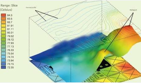
    Figure: Temperature variation on a horizontal plane in a design example

    1. Using a single supply value and a single QJA value for the package to calculate the maximum temperature of the die. This temperature value is usually too optimistic and does not capture the hot spot effects on the die.
    2. Estimating power and voltage drop without considering local temperature changes. Leakage power, a major component of total power, is exponentially related to temperature, and a small change in temperature can cause a large change in leakage power. This power change also causes a significant change in voltage drop along the power supply line.
    3. Checking the timing performance of the chip using boundary analysis tools that assume a single uniform chip temperature. Temperature differences of more than 10°C plus the voltage drop changes mentioned above will cause significant changes in cell delays. In addition, the increasingly obvious delay reversal effects may also cause problems in setup time analysis.
    4. Performing reliability analysis without considering temperature variations along the metal interconnects. The mean time to failure of traces is exponentially related to temperature, which can lead to overly optimistic designs that cause products to fail prematurely in the field.
    5. Designing chip packages without checking the presence and number of hot spots on the die. Hot spots can severely affect the efficiency of cooling materials, leading to excessive operating temperatures on the device.
    Contact us for PCB quote now |
    Post Tags: #aluminum clad pcb#aluminum core pcb#aluminum core pcb led#aluminum pcb#assemble pcb

    Post navigation

    Previous Previous
    PCB Design to Assembly: Key Steps for Efficient Fabrication
    NextContinue
    Top Mobile Charger PCB Manufacturers for Reliable Power Solutions

    Search

    Search

    Products

    • HDI Multilayer PCB
    • Rigid Flex PCB
    • Flex pcb
    • High Frequency PCB
    • High speed pcb
    • Heavy copper PCB
    • Metal Core PCB
    • Ceramic PCB

    Address

    Andwin Circuits Co.,Limited
    Email: sales@andwinpcb.com
    Tel: +86 755 2832 9394
    Fax:+86 755 2992  6717
    ADD:1-2F-1217,HouDeQun Industrial park,
    NanTing RD NO.56,ShaJing,BaoAn,Shenzhen 518104,GuangDong,China

    Products

    • HDI Multilayer PCB
    • Rigid Flex PCB
    • Flex pcb
    • High Frequency PCB
    • High speed pcb
    • Heavy copper PCB
    • Metal Core PCB
    • Ceramic PCB

    Technology

    • Blogs
    • Via in pad
    • PCB E-test
    • PCB stack up
    • Metal core PCB panelization
    • Controlled impedance PCB

    CERTIFICATION

    Certification >>


    Copyright© 2003 - 2026 Andwin | All Rights Reserved | Powered by Andwin

    Scroll to top
    • Home
    • Products
      • HDI multilayer PCB
      • Rigid Flex PCB
      • Flex pcb
      • Special PCB
        • High Frequency PCB
          • Rogers RO4350B PCB
          • Rogers RO4003 pcb
          • Rogers RO3003 PCB
          • Rogers 5880 PCB
          • DICLAD 527 PCB
          • Taconic TLX series
          • Taconic TLX-8 RF PCB
          • Taconic TLX-9 RF PCB
        • High speed pcb
          • Megtron 6 High Speed PCB
          • TU-872 SLK Sp High Speed
        • High TG PCB
          • SHENGYI SH260 PCB
          • ISOLA 370HR PCB
          • ISOLA IS410 PCB
          • ISOLA IS420 PCB
        • Heavy copper PCB
        • Copper coin pcb
        • Copper inlay PCB
      • Metal Core PCB
        • Copper core pcb
        • Aluminum PCB
        • 2 Layers Aluminum PCB
        • Direct thermal MCPCB
        • 2 Layers Direct Thermal
      • Ceramic PCB
        • DPC ceramic PCB
        • DBC ceramic PCB
        • Thick film Ceramic PCB
        • Al2O3 Alumina PCB
        • AIN ALN ceramic PCB
        • IGBT Ceramic PCB
    • Service
      • PCB Assembly
      • Quick turn PCB assembly
      • PCBA conformal coating
    • Industry
      • Telecommunication
      • IoT and Wireless
      • Industrial Control
      • Thermal management
      • Power and Energy
      • IC test board
      • Automative
      • Medical
    • Capability
      • Rigid PCB
      • Rigid flex PCB
      • Metal core PCB
      • PCB Assembly
    • Technology
      • Blogs
      • Via in pad
      • PCB E-test
      • PCB stack up
      • MCPCB panelization
      • Controlled impedance PCB
    • About
      • About us
      • Certification
      • Factory Tour
    • Contact
    Search