
Choosing the Right Power IC to Optimize PCB Layout
Introduction
In modern electronic design, selecting the appropriate power management integrated circuit (IC) is crucial for optimizing printed circuit board (PCB) performance. Power ICs regulate voltage, manage power distribution, and ensure efficient energy conversion, directly impacting system reliability, thermal performance, and electromagnetic compatibility (EMC). A well-chosen power IC simplifies PCB layout, reduces noise, and minimizes power losses.
This article explores key considerations when selecting power ICs to optimize PCB design, including efficiency, thermal management, footprint, switching frequency, and integration level.
1. Understanding Power IC Requirements
Before selecting a power IC, designers must define the system’s power requirements:
- Input & Output Voltage Range – Determines whether a buck, boost, buck-boost, or LDO regulator is needed.
- Current Requirements – High-current applications may need multi-phase regulators or external MOSFETs.
- Efficiency Needs – Switching regulators (e.g., DC-DC converters) offer higher efficiency than linear regulators (LDOs) but may introduce noise.
- Transient Response – Fast load-changing applications (e.g., processors) require regulators with quick transient response.
2. Impact of Power IC Selection on PCB Layout
2.1 Efficiency and Thermal Management
High-efficiency power ICs reduce heat dissipation, simplifying thermal management. Switching regulators (90%+ efficiency) generate less heat than LDOs, which dissipate excess voltage as heat. However, switching regulators introduce high-frequency noise, requiring careful PCB layout.
PCB Layout Tips:
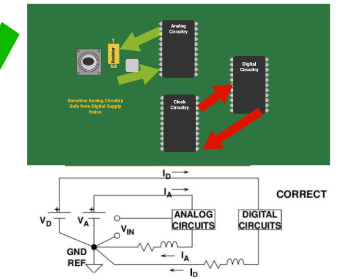
- Place high-current paths away from sensitive analog circuits.
- Use thermal vias under ICs to dissipate heat.
- Ensure adequate copper area for heat sinking.
2.2 Switching Frequency and Noise
Switching regulators operate at frequencies ranging from tens of kHz to several MHz. Higher frequencies allow smaller inductors and capacitors but increase switching losses and EMI.
PCB Layout Tips:
- Keep high-frequency switching loops short to minimize radiated noise.
- Use ground planes to shield sensitive signals.
- Place input/output capacitors close to the IC.
2.3 Integration Level
Highly integrated power ICs (e.g., those with built-in MOSFETs, compensation networks, and protection features) reduce external component count, saving PCB space and simplifying design. However, they may limit flexibility in high-power applications.
PCB Layout Tips:
- Follow manufacturer-recommended layouts for integrated regulators.
- Ensure proper decoupling capacitor placement.
3. Key Power IC Selection Criteria
3.1 Topology (Buck, Boost, LDO, etc.)
- Buck Converters – Step-down voltage; efficient but noisy.
- Boost Converters – Step-up voltage; useful for battery-powered devices.
- Buck-Boost Converters – Handles varying input voltages (e.g., battery applications).
- LDOs – Low noise but inefficient for large voltage drops.
3.2 Package and Footprint
Smaller packages (e.g., QFN, DFN) save space but may complicate thermal management. Larger packages (e.g., TO-220) handle more heat but increase PCB size.
3.3 Protection Features
Look for ICs with:
- Overcurrent protection (OCP)
- Overvoltage protection (OVP)
- Thermal shutdown
- Undervoltage lockout (UVLO)
4. PCB Layout Optimization Techniques
4.1 Minimizing Parasitic Inductance
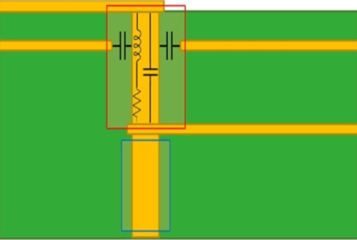
High di/dt loops in switching regulators can induce voltage spikes. To mitigate:
- Keep power traces short and wide.
- Use ground planes for return paths.
4.2 Proper Grounding
- Use a star ground for analog and digital sections.
- Avoid ground loops by ensuring low-impedance return paths.
4.3 Component Placement
- Place input capacitors near the IC’s VIN pin.
- Position feedback resistors close to the regulator.
- Route sensitive signals away from switching nodes.
5. Case Study: Optimizing a Buck Converter Layout
Consider a 12V-to-3.3V buck converter:
- IC Selection – Choose a synchronous buck converter with integrated FETs (e.g., TI’s TPS54332).
- Input Capacitors – Place ceramic capacitors near the VIN pin.
- Inductor Placement – Keep it close to the SW pin to minimize loop area.
- Output Capacitors – Use low-ESR ceramics near the VOUT pin.
- Thermal Management – Add thermal vias under the IC’s exposed pad.
6. Conclusion
Selecting the right power IC significantly impacts PCB performance. By considering efficiency, thermal management, switching frequency, and integration level, designers can optimize layout for noise reduction, thermal dissipation, and power integrity. Following best practices in component placement and grounding ensures reliable operation.
By carefully evaluating power ICs and applying smart PCB layout techniques, engineers can achieve compact, efficient, and robust power delivery networks in their designs.