Four Steps to Checking for Shorts in PCBs
How to check for shorts in PCBs during PCB design:You can take the following important steps to detect shorts in PCBs:1.Find the short in the PC;2.Test the circuit for the short on the board;3.Find the faulty component on the PCB;4.Destructively test the PCB.
Step 1:How to Find a Short in a PCB
Visual Inspection
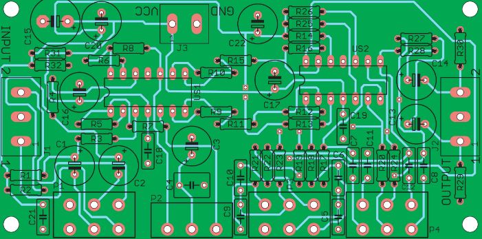
The first step is to carefully inspect the entire surface of the PCB.Use a magnifying glass or low-power microscope of necessary.Look for tin whiskers between pads or solder joints.Any cracks or specks in the solder should be noted.Inspect all through-holes.If unplated through-holes are specified,ensure that they are present o the board.Poorly plated vias can create shorts between layers and tie everything to ground,VCC,or both.If the short is truly severe and cause components to reach critical temperatures,you will actually see burn marks on the PCB.These may be small,but they will appear brown instead of the normal green solder resist.If you habe multiple boards,a burned PCB can help you narrow down a specific location without having to power another board and compromise your search range. Unfortunately,we didn’t have any burns on the board itself;it was just an unlucky finger checking for overheating on an integrated circuit.Some shorts will occur internally on the board and won;t produce a burn.This also means they won’t produce a burn.This also means they won’t be noticeable on surface layers.Here,you’ll need other methods to detect shorts in the PCB.
Infrared Imaging
Using an infrared camera can helo you locate areas generating significant heat.If you don’t see active components away from the hot spot,a PCB short could be present,even if it’s between internal layers.A short circuit typically has higher resistance than a normal trace or solder joint,as it doesn’t benefit from optimization in the design(unless you ‘re really keen on ignoring rule checking).This resistance,along with the naturally high current drawn by a direct connection between power and ground ,means the conductor in the PCB short will heat up.Start with a low current that you can use. Ideally,you’ll see the short before it causes more damage.
The finger test is one way to check if a specific component is overheating.
Step2:How to Test for a Short Circuit on an Electronics Board
Beyond the first step of inspecting the circuit board with your trusty eyes,you can use several other methods to identify potential cause of PCB shorts.
Testing with a Digital Multimeter
To test a circuit board for a short circuit,you need to check the resistance between different points in the circuit.If a visual inspection doesn’t reveal any clues as to the location or cause of the short is detected.For example,if you measure the resistance between adjacent traces or pads on a PCB, you should expect a high resistance.If you measure the resistance between adjacent traces or pads on a PCB,You should expect a high resistance,If you measure very low resistance between two conductors that should be in separate circuits,there’s a possibility of internal or external bridging between the two conductors.Note that two adjacent traces or pads bridged by an inductor(such as in an impedance matching network or discrete filter circuit)will produce a very low resistance reading,as the inductor is simply a coiled conductor.However,if the two conductors on the board are far apart and you read a low resistance,then there is a bridge somewhere on the board.
Testing Relative to Ground
Of particular concern are shorts involving ground vias or ground planes.Multilayer PCBS with internal ground planes will include a return path through the componet near the via,providing a convenient location to check all other vias and pad on the board’s surface layers.Place one probe on the ground connection and touch the other probe to another conductor on the board.This same ground connection will exist elsewhere on the board,meaning that if you touch each probe to two different ground vias,the reading will be very low.Be careful with your layout when doing this,as you don’t want to mistake a short for a common ground connection.All other ungrounded,exposed conductors should have a high resistance between the common ground connection and the conductors itself.If the reading is low and there is no inductance between the conductor in question and ground,you may have a damaged component or a short.
Multimeter probes can help locate shorts,but they aren’t always sensitive enough to detect them.
Component Shorts
Checking for component shorts also involves measuring resistance with a multimeter.If a visual inspection doesn’t reveal excess solder or metal flakes between pads,a short may be forming on an inner layer between two pads/pin on the component.Shorts between pads/pins on a component can also occur due to poor manufacturing.This is one reason why PCBs should undergo Design for Measuremwnt(DFM) and Design Rule Checks.Pads and vias that are too close together can accidentally bridge or short during the manufacturing process.Here,you need to measure the resistance between pins on an IC or connector.Adjacent pins are particularly prone to shorts,but these aren;t the only places where shorts can form.Check the resistance between pads/pins relative to each other and that ground connection has low resistance.
Check the resistance between the ground header,connector,and other pins on the IC.Shown here is a USB connector
Narrowing Down the Location
If you suspect a short is between two conductors or between a conductor and ground,you can narrow the location by inspecting nearby conductors.Connect one lead of the multimeter to the suspected shorted connection,move the other lead to a different nearby ground connection,and check the resistance as you move the ground further away.If the resistance increases,you’re moving the grounded wire further away from the shorted location.This can help you narrow down the exact location of the short,even to a specific pair of pads/pins on the component.
Step 3:How to Find a Faulty Component on a PCB
Faulty components or improperly installed components can cause a short,leading to numerous problems on a circuit board.Your component could be defective or counterfeit,causing a short or short.
Defective Component
Some components,such as electrolytic capacitors,are prone to deterioration.If you have suspicious component,inspect them first.If you’re unsure ,a quick Google search for the suspected”failed”component can often reveal whether this is a common problem.If you measure very low resistance between two pads/pins(neither of which is a ground or power pin),the short is likely caused by a burned-put component.This is a clear indicator that the capacitor is bad.Capacitors also swell when they deteriorate when the applied voltage exceeds their breakdown threshold.
See the bulge on the top of this capacitor?This indicates the capacitor is damaged.
Step 4:How to Destructively Test a PCB
Destructive testing is obviously a last resort.If you have access to an X-ray imaging device,you can inspect the interior of the circuit board without destroying it.If you don’t have X-ray equipment,you can begin removing components and running the multimeter test again.This helps in two ways.First,it makes it easier to access the pads(including thermal pads)that may be shorting.Second,it eliminates the possibility that the fault is causing the short,allowing you to focus on the conductors.If you manage to narrow the short to a connection on a component(for example,between two pads),it may not be obvious whether the component is defective or if there’s a short somewhere inside the board.At this point,you may need to remove the componet and inspect the pads on the board.Removing the component allows you to test whether the component itself is defective or if the pads on the board are bridging internally.
If the location of the short(or possibly multiple shorts)remains elusive,you can cut open the board and try to narrow it down.if you have a good idea of the general location of the short,you can cut a section of the circuit board and repeat the multimeter to check for shorts in specific locations.If you’ve reached this point,your short is particularly elusive.This will at least allow you to narrow the short down to a specific area of the circuit board.