
Good Grounding Guidelines for PCB Design
Grounding is undoubtedly one of the most difficult issues in system design. Although it is relatively simple in concept, it is complex to implement. Unfortunately, there is no concise, step-by-step method to ensure good results, but if some details are not handled correctly, they can cause headaches.
“ground” is the reference point for signals.
For linear systems, “ground” is the reference point for signals. Unfortunately, in unipolar power systems, it also becomes the return path for power supply currents. The performance of high-precision linear systems can be seriously damaged if the grounding strategy is not applied properly.
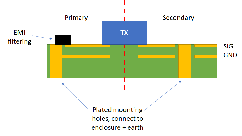
Grounding is an issue that cannot be ignored for all analog designs, and it is equally important to implement it properly in PCB-based circuits. Fortunately, some high-quality grounding principles, especially the use of ground planes, are inherent to the PCB environment. Because this factor is one of the significant advantages of PCB-based analog design, we will focus on it in this article.
There are other aspects of grounding that must be managed, including controlling stray ground and signal return voltages that can degrade performance. These voltages can be caused by external signal coupling, common currents, or simply excessive IR drops in ground conductors. Proper routing, routing dimensions, as well as differential signal processing and ground isolation techniques allow us to control such parasitic voltages.
An important topic we will discuss is grounding techniques for analog/digital mixed signal environments. In fact, the issue of high-quality grounding can—and must—affect the entire layout principles of mixed signal PCB design.
The importance of using the good high-speed circuit design techniques
Today’s signal processing systems generally require mixed signal devices such as analog-to-digital converters (ADCs), digital-to-analog converters (DACs), and fast digital signal processors (DSPs). The need to process analog signals with a wide dynamic range necessitates the use of high-performance ADCs and DACs. Maintaining a wide dynamic range and low noise in a harsh digital environment is closely related to the use of good high-speed circuit design techniques, including proper signal routing, decoupling, and grounding.
In the past, “high-precision, low-speed” circuits were generally considered different from so-called “high-speed” circuits. For ADCs and DACs, the sampling (or update) frequency was generally used as the speed criterion. However, the following two examples show that in practice, most of today’s signal processing ICs are truly “high-speed” and must be treated as such devices to maintain high performance. This is true for DSPs, ADCs, and DACs.
All sampling ADCs (ADCs with built-in sample-and-hold circuits) suitable for signal processing applications operate with high-speed clocks with fast rise and fall times (typically a few nanoseconds) and must be considered high-speed devices even if the throughput seems low. For example, a moderate-speed 12-bit successive approximation register (SAR) ADC can operate with a 10 MHz internal clock and only sample at 500 kSPS.
Sigma-delta ADCs have high oversampling ratios and therefore also require high-speed clocks.
Even high-resolution, so-called “low-frequency” industrial measurement ADCs (such as the AD77xx-series) with throughput rates of 10 Hz to 7.5 kHz operate with clock frequencies of 5 MHz or higher and provide up to 24 bits of resolution.
Further complicating matters, mixed-signal ICs have both analog and digital ports, so the use of proper grounding techniques becomes even more intricate. In addition, some mixed-signal ICs have relatively low digital currents, while others have high digital currents. In many cases, these two types of ICs require different treatments for optimal grounding.
Digital and analog design engineers tend to look at mixed-signal devices from different perspectives, and this article aims to explain general grounding principles that apply to most mixed-signal devices without having to understand the specific details of the internal circuits.
From the above, it is obvious that there is no quick manual for grounding. Unfortunately, we cannot provide a list of techniques that will guarantee grounding success. We can only say that ignoring some things may cause problems. What works well in one frequency range may not work in another frequency range. There are also conflicting requirements. The key to dealing with grounding problems is to understand how current flows.