
How to Avoid Electromagnetic Issues in PCB Design
Introduction
Printed Circuit Board (PCB) design is a critical aspect of electronic product development. One of the most challenging problems engineers face is electromagnetic interference (EMI) and electromagnetic compatibility (EMC). Poor PCB design can lead to signal integrity issues, crosstalk, radiated emissions, and susceptibility to external noise, ultimately affecting device performance and regulatory compliance.
This article explores key strategies to avoid electromagnetic problems in PCB design, covering layout techniques, grounding, shielding, component placement, and routing best practices.
1. Proper Grounding Techniques
1.1 Use a Solid Ground Plane
A continuous ground plane provides a low-impedance return path for high-frequency signals, reducing EMI. Multilayer PCBs should dedicate at least one layer to a solid ground plane.
1.2 Avoid Ground Loops
Ground loops occur when multiple return paths create circulating currents, leading to noise. Solutions include:
- Single-point grounding for low-frequency circuits.
- Multi-point grounding for high-frequency circuits.
- Star grounding to centralize return paths.
1.3 Split Ground Planes Carefully
While separating analog and digital grounds can reduce noise, improper splits can worsen EMI. Use a single ground plane with partitioned sections connected at a single point to prevent voltage differences.
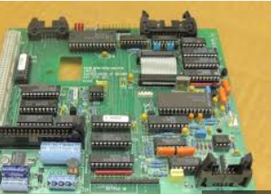
2. Signal Integrity and Routing Best Practices
2.1 Controlled Impedance Routing
High-speed signals (e.g., USB, HDMI, DDR) require controlled impedance to prevent reflections and signal degradation:
- Use microstrip or stripline configurations.
- Match trace width and dielectric properties to target impedance (e.g., 50Ω, 90Ω differential).
2.2 Minimize Crosstalk
Crosstalk occurs when adjacent traces induce unwanted signals. Mitigation techniques:
- Increase spacing between parallel traces (3W rule: space traces ≥3× the trace width).
- Route sensitive signals orthogonally to reduce coupling.
- Use guard traces or ground shielding between critical signals.
2.3 Avoid Sharp Corners
Right-angle bends increase capacitance and reflections. Instead, use 45° angles or curved traces for smoother transitions.
3. Power Distribution Network (PDN) Design
3.1 Decoupling Capacitors
High-frequency noise on power rails can propagate EMI. Proper decoupling involves:
- Placing 0.1µF ceramic capacitors near IC power pins.
- Using bulk capacitors (10µF–100µF) for low-frequency stabilization.
- Implementing multiple capacitor values to cover a wide frequency range.
3.2 Power Plane Design
- Use dedicated power planes in multilayer PCBs.
- Avoid splits in power planes; instead, use copper pours for uniform distribution.
- Ensure low-impedance paths between power and ground planes.
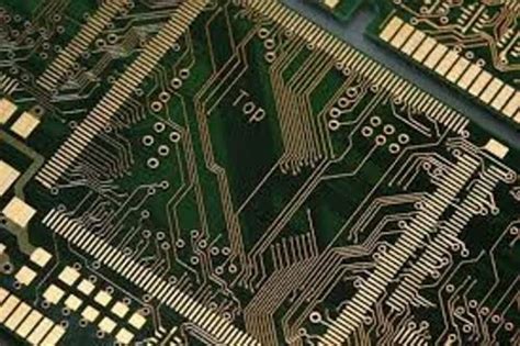
4. Component Placement Strategies
4.1 Separate Analog and Digital Sections
- Keep analog components (sensors, amplifiers) away from digital components (microcontrollers, FPGAs).
- Use moats (isolated ground regions) for sensitive analog circuits.
4.2 High-Speed Components Near Connectors
Place high-speed interfaces (Ethernet, USB) close to their connectors to minimize trace lengths and reduce EMI radiation.
4.3 Clock Signal Management
Clock signals are major EMI sources. Best practices:
- Keep clock traces short and direct.
- Use series termination resistors to dampen ringing.
- Avoid routing clocks near sensitive signals.
5. EMI Shielding and Filtering
5.1 Shielding Cans
For high-frequency circuits (RF, wireless modules), metal shielding cans block radiated emissions.
5.2 Ferrite Beads and Filters
- Use ferrite beads on power lines to suppress high-frequency noise.
- Implement LC filters for noise-sensitive analog inputs.
5.3 EMI Gaskets and Conductive Coatings
In high-EMI environments, conductive coatings or gaskets can prevent interference.
6. PCB Stackup Considerations
6.1 Multilayer Stackup Design
A well-designed stackup minimizes EMI:
- 4-layer PCB: Signal – Ground – Power – Signal.
- 6-layer PCB: Signal – Ground – Signal – Power – Ground – Signal.
- 8+ layer PCBs: Add additional ground/power planes for better noise control.
6.2 Return Path Optimization
Ensure high-speed signals have an adjacent ground plane for a clear return path.
7. Testing and Validation
7.1 Pre-Compliance EMC Testing
Use near-field probes and spectrum analyzers to detect EMI early.
7.2 Signal Integrity Simulations
Tools like SPICE, HyperLynx, or Ansys SIwave predict EMI issues before fabrication.
7.3 Compliance Testing
Ensure the design meets FCC, CE, or CISPR standards for radiated/conducted emissions.
Conclusion
Avoiding electromagnetic issues in PCB design requires a combination of proper grounding, controlled impedance routing, strategic component placement, and effective shielding. By following these best practices, engineers can minimize EMI, improve signal integrity, and ensure compliance with regulatory standards. Continuous testing and simulation further refine designs, leading to robust and reliable electronic products.
By implementing these techniques, PCB designers can significantly reduce electromagnetic problems, enhancing both performance and reliability in modern electronics.