How to Disassemble a Printed Circuit Board (PCB): A Step-by-Step Guide
Introduction
Printed Circuit Boards (PCBs) are the backbone of modern electronics, found in everything from smartphones to industrial machinery. Whether you’re repairing, recycling, or reverse-engineering a device, knowing how to properly disassemble a PCB is essential. This guide provides a detailed, step-by-step approach to safely and effectively dismantling a PCB while minimizing damage to components and ensuring personal safety.
1. Safety Precautions
Before disassembling any PCB, follow these safety measures:
1.1 Power Disconnection
- Unplug the device from any power source.
- If working with a battery-powered device, remove the battery.
- Discharge capacitors using a resistor or a discharge tool to avoid electric shocks.
1.2 Personal Protective Equipment (PPE)
- Wear anti-static wrist straps to prevent electrostatic discharge (ESD) damage.
- Use safety goggles to protect against flying debris.
- Work in a well-ventilated area if dealing with soldering fumes.
1.3 Workspace Preparation
- Use an ESD-safe mat to prevent static damage.
- Keep tools organized to avoid losing small components.

2. Tools Required for PCB Disassembly
Gather the following tools before starting:
- Soldering iron (temperature-controlled, 25-60W)
- Desoldering pump (solder sucker) or desoldering braid
- Tweezers (ESD-safe, non-magnetic)
- Screwdrivers (Phillips, flathead, Torx, etc.)
- PCB holder or vise (to stabilize the board)
- Heat gun or hot air rework station (for surface-mount components)
- Flux (rosin or no-clean) to aid desoldering
- Isopropyl alcohol & brush (for cleaning residue)
- Multimeter (for testing components)
3. Step-by-Step PCB Disassembly Process
3.1 Removing the PCB from the Enclosure
- Identify and remove all screws holding the device together.
- Use a plastic spudger to pry open clips without damaging the casing.
- Carefully disconnect any ribbon cables or connectors using tweezers.
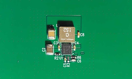
3.2 Inspecting the PCB
- Take high-resolution photos of the PCB for reassembly reference.
- Note the orientation of polarized components (capacitors, diodes, ICs).
- Identify any damaged traces or burnt components before proceeding.
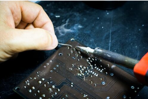
3.3 Desoldering Through-Hole Components
- Apply flux to the solder joints to improve heat transfer.
- Heat the joint with a soldering iron (350-400°C).
- Use a desoldering pump to remove molten solder.
- Gently wiggle the component with tweezers to free it.
- Repeat for all pins before fully removing the component.
Tip: For stubborn joints, add fresh solder to improve heat conduction before desoldering.
3.4 Removing Surface-Mount Components (SMDs)
- For small SMDs (resistors, capacitors):
- Use a soldering iron with a fine tip and drag solder technique.
- Alternatively, use hot air (300-350°C) to melt solder evenly.
- For ICs (QFP, BGA packages):
- Apply flux around the pins.
- Use a hot air rework station (350-400°C) in circular motions.
- Lift the IC with tweezers once the solder liquefies.
Warning: Excessive heat can damage the PCB or nearby components.
3.5 Handling Multi-Layer and High-Density PCBs
- Use a preheater (if available) to evenly warm the PCB and prevent warping.
- Work slowly to avoid tearing delicate traces.
- For BGA chips, consider using a BGA rework station for precise heating.
4. Post-Disassembly Steps
4.1 Cleaning the PCB
- Use isopropyl alcohol (90%+ purity) and a soft brush to remove flux residue.
- Avoid abrasive cleaners that can damage solder masks.
4.2 Testing Salvaged Components
- Check resistors, capacitors, and diodes with a multimeter.
- Verify ICs using a component tester or datasheet references.
4.3 Organizing Components
- Store removed parts in anti-static bags or labeled containers.
- Group similar components (e.g., resistors, capacitors) for easy retrieval.
5. Common Mistakes to Avoid
❌ Applying excessive force – Can break PCB traces or components.
❌ Overheating joints – May lift copper pads or damage nearby parts.
❌ Skipping ESD protection – Static can destroy sensitive ICs.
❌ Rushing the process – Leads to misplaced or lost components.
6. Advanced Techniques
6.1 Using a Desoldering Station
- Combines a soldering iron and vacuum pump for efficient solder removal.
- Ideal for high-precision work (e.g., removing multi-pin connectors).
6.2 Infrared Rework Systems
- Provides localized heating without airflow disturbances.
- Best for complex PCBs with heat-sensitive components.
6.3 PCB Trace Repair
- If a trace is damaged during disassembly:
- Use conductive epoxy or jumper wires to reconnect broken paths.
- Apply solder mask to protect repaired areas.
7. Environmental & Recycling Considerations
- Dispose of solder waste properly (lead-based solder is hazardous).
- Recycle PCBs at certified e-waste facilities.
- Salvage reusable components to reduce electronic waste.
Conclusion
Disassembling a PCB requires patience, the right tools, and proper techniques. Whether you’re repairing, recycling, or learning electronics, following these steps ensures a safe and efficient process. Always document your work, handle components carefully, and prioritize safety to achieve the best results.
By mastering PCB disassembly, you gain deeper insight into electronics and enhance your troubleshooting and repair skills. Happy tinkering!