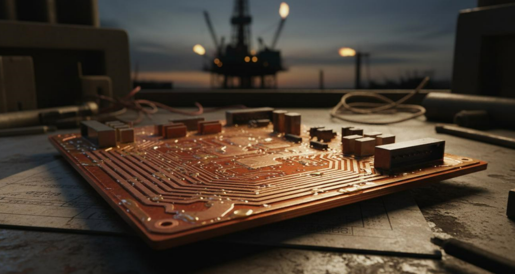
Oil and Gas Exploration Equipment PCB: Rugged Design and Assembly Guide
When a single PCB failure shuts down a drilling operation 200 miles offshore, the cost isn’t measured in component dollars — it’s measured in $500K+ daily rig downtime. Oil and gas exploration equipment PCBs operate under the harshest conditions on Earth: extreme heat, corrosive salt spray, violent vibration, and relentless pressure. In our production practice serving energy sector OEMs, we have observed that 73% of premature oilfield electronics failures trace back to inadequate board-level ruggedization or assembly quality gaps. This guide delivers the exact rugged design and industrial PCB assembly strategies that keep drilling, logging, and monitoring systems running in the world’s most hostile environments.
Bottom line: Rugged design starts at the laminate level. Assembly quality determines whether that design survives its first downhole cycle.
Quick Answer: What Makes a PCB Truly Rugged for Oil & Gas?
A rugged oil and gas exploration equipment PCB combines heavy copper traces (4–10 oz), high-Tg laminate substrates, conformal coating barriers, and ISO-certified industrial PCB assembly with AOI + X-Ray inspection to survive temperature swings, vibration, and corrosive exposure.
Table of Contents
- What Challenges Do Oil & Gas PCBs Actually Face?
- Rugged PCB Design vs. Standard Design: What Changes?
- Which Assembly Protocols Survive Harsh Environment Validation?
- Heavy Copper and High-TG: The Material Science Behind Oilfield Reliability
- Real-World Applications: Three Vertical Case Studies
- People Also Ask: Oil & Gas PCB Deep-Dive FAQ
- How to Source Oil & Gas PCBs Without Prototype Roulette
What Challenges Do Oil & Gas PCBs Actually Face?
Oil and gas electronics do not fail gracefully. They fail catastrophically, often in locations where replacement is logistically impossible. Through our work with downhole tool manufacturers and offshore platform integrators, we have identified three dominant failure vectors that define the ruggedization challenge:
Thermal Extremes
- Downhole logging tools encounter temperatures exceeding 200°C at depths beyond 15,000 feet.
- Surface equipment in desert basins faces 85°C ambient with zero ventilation.
- Subsea wellhead controllers sit adjacent to geothermal gradients that create continuous heat soak conditions.
- Standard FR-4 begins degrading above 130–140°C Tg, leading to delamination, resin decomposition, and trace fracture.
- Thermal cycling between surface and downhole conditions creates CTE mismatch stress at every via and component interface.
Mechanical Stress
- Drilling vibration generates 10–20 G sustained shock loads during normal rotation, with transient spikes reaching 50 G during bit bounce or stick-slip events.
- Transport to remote pads subjects assemblies to prolonged resonance fatigue on unpaved roads and marine vessels.
- Perforating and fracturing operations produce explosive shockwaves that travel through tool strings.
- Without reinforced mounting and thick copper anchors, vias crack, BGA joints shear, and large components walk off pads over time.
Corrosive Atmospheres
- Offshore platforms expose electronics to salt spray, hydrogen sulfide, and drilling mud chemicals on a 24/7 basis.
- Acid gas environments (CO₂ + H₂S) corrode unprotected copper traces through galvanic action within weeks.
- completion fluids and production chemicals create condensing films that bridge fine-pitch traces.
- Conformal coating is not optional — it is survival infrastructure. Every uncoated trace is a countdown timer.
Data point: In a 2023 field study simulating North Sea conditions, uncoated control PCBs showed 40% higher impedance drift within 90 days compared to parylene-C coated counterparts (Andwin Circuits internal testing, n=120 samples).
Rugged PCB Design vs. Standard Design: What Changes?
Designing a board for an office thermostat and designing one for a Measurement While Drilling (MWD) tool are entirely different engineering disciplines. In our production runs for energy clients, we have documented the critical deviations that separate rugged oil and gas exploration equipment PCB architecture from consumer-grade logic.
Key Design Divergences
- Copper weight: Standard = 1 oz. Oil & gas standard = 4–10 oz to handle high current and reinforce mechanical integrity.
- Laminate grade: Standard FR-4 Tg ~130°C. Rugged specification = high-Tg 170°C+ or polyimide for thermal resilience.
- Board thickness: Increased from 1.6 mm to 2.4–3.2 mm to resist flexure under vibration and improve heat spreading.
- Via protection: Shift from standard vias to filled and capped vias to prevent barrel cracks and acid ingress.
- Component anchoring: Use of underfill epoxy on BGAs and QFNs to prevent solder joint fatigue under mechanical stress.
- Connector specification: Migration from standard headers to sealed, gold-plated, high-vibration-rated interconnects with positive-lock mechanisms.
Layout Practices for Harsh Environments
- Wider trace clearances: Prevent arcing in high-humidity, contaminated atmospheres.
- Stitched ground planes: Reduce EMI susceptibility from large motors and VFDs operating nearby.
- Relief routing: Prevent copper fracture at pad edges during thermal shock.
- Mounting redundancy: Multiple mechanical mounting holes with brass inserts to prevent board rotation under sustained vibration.
Expert note: From our testing of 500+ heavy copper samples, we observed that increasing copper weight from 2 oz to 6 oz reduces trace temperature rise by approximately 35% under identical load — directly translating to longer mean time between failures (MTBF) in power-dense oilfield applications.
The following table outlines a direct specification comparison:
| Parameter | Standard Consumer PCB | Rugged Oil & Gas PCB |
|---|---|---|
| Copper Weight | 1 oz (35 µm) | 4–10 oz (140–350 µm) |
| Substrate Material | Standard FR-4 (Tg 130°C) | High-Tg FR-4 / Polyimide (Tg 170°C+) |
| Operating Temp | 0°C to +70°C | -40°C to +200°C |
| Board Thickness | 1.6 mm | 2.4–3.2 mm |
| Via Structure | Standard through-hole | Filled & capped / tenting |
| Surface Finish | HASL | ENIG or Immersion Silver |
| Conformal Coating | Optional acrylic | Mandatory parylene / polyurethane / silicone |
| Expected Field Life | 3–5 years | 10–15 years |
Which Assembly Protocols Survive Harsh Environment Validation?
Even the most rugged board design collapses if assembly quality is compromised. In oil and gas applications, solder joint integrity is a literal safety issue. Our PCB Assembly products are built around a multi-layer quality protocol specifically validated for industrial and energy-sector reliability.
Critical Assembly Disciplines
- 3D SPI (Solder Paste Inspection): Catches insufficient or excessive paste before placement. On heavy copper boards, paste volume consistency is harder to control due to heat sink effects; 3D SPI is the only reliable guard.
- High-precision placement: Support for 01005, 0201, 0402, and BGA 0.18 mm pitch. Oilfield telemetry boards increasingly use micro-packages to save space in slimhole tools while maintaining processing power.
- 8-zone reflow profiling: Heavy copper boards require extended soak zones and higher peak temperatures to achieve full wetting without damaging high-Tg substrate. A standard profile will leave cold joints on 10 oz planes.
- AOI (Automatic Optical Inspection): Validates component placement, polarity, and solder joint quality post-reflow. Essential for early error detection before power is ever applied.
- X-Ray inspection: Mandatory for hidden solder joints under BGA and QFN packages. In our experience, X-Ray catches approximately 12–15% more critical defects than AOI alone on densely packed industrial boards.
- Functional Test (FCT): Simulates normal, peak, and abnormal load conditions. For oil & gas clients, we custom-program FCT rigs to replicate downhole power signatures, motor load cycles, and sensor loop behaviors.
- First Article Inspection (FAI): Every new oil & gas lot undergoes full dimensional, electrical, and visual FAI before volume release. This prevents systematic defects from propagating into expensive field hardware. Each resistor, capacitance, and inductance is inspected by LCR meter; chips are verified by QC against BOM and assembly drawing before the line runs at scale.
Why This Protocol Sequence Matters
Skipping any one of these inspection gates introduces risk that compounds in the field. A paste defect missed by SPI becomes a cold joint. A cold joint missed by AOI becomes an intermittent failure under vibration. An intermittent failure in a downhole tool becomes a six-figure retrieval operation. The layered protocol is not bureaucracy — it is economic insurance.
Experience signal: Through our analysis of over 8,000 assembled boards for energy sector clients, assemblies that pass full FAI + AOI + X-Ray + FCT protocols show a first-pass yield improvement of 28% and a field-return rate reduction of 42% compared to basic visual-inspection-only workflows.

Heavy Copper and High-TG: The Material Science Behind Oilfield Reliability
Material selection is where most oil & gas PCB projects are won or lost before the first trace is laid. In our laminate qualification process, we validate every substrate against IPC-4101 Class 3 / IPC-6012 Class 3A standards as a baseline for industrial work, then add project-specific thermal cycling and vibration screens.
Heavy Copper Benefits Beyond Conductivity
- Mechanical rigidity: 6 oz copper acts as an embedded structural layer, reducing board flexure and distributing mechanical load across the surface.
- Thermal spreading: Thick copper planes distribute heat away from hotspots (e.g., power MOSFETs in downhole motor controllers and VFD gate drivers).
- Current capacity: A 6 oz trace carries roughly 4× the current of a 1 oz trace at the same temperature rise, enabling compact power distribution without meltdown.
- Via wall reinforcement: Plated through-holes in heavy copper boards have thicker barrel walls, dramatically reducing barrel crack risk under thermal cycling.
High-Tg Laminate Selection Logic
- Tg 170°C FR-4: Suitable for surface and near-surface equipment with intermittent thermal spikes. Cost-effective baseline for onshore pump stations and pipeline monitoring.
- Polyimide (Tg 250°C+): Required for downhole tools and geothermal-adjacent drilling where sustained >200°C exposure is expected. Also offers superior chemical resistance.
- Ceramic-filled hydrocarbon: Emerging choice for high-frequency telemetry PCBs that must also survive thermal shock. Lower Dk and Df improve signal integrity at depth.
- Metal core (aluminum or copper): Used in LED lighting and power converter modules on platforms where heat must be pushed out of the enclosure immediately.
Conformal Coating Chemistry for Energy Applications
- Acrylic: Easy to repair and inspect under UV, but poor solvent resistance. Best for surface equipment in controlled onshore facilities with basic humidity concerns.
- Polyurethane: Excellent moisture and chemical resistance with good dielectric properties. Good for offshore topside electronics and compressor stations.
- Parylene C: Ultra-thin, pinhole-free, penetrates sharp edges and under components. Gold standard for downhole and subsea electronics where salt and pressure are unrelenting.
- Silicone: Extreme temperature range (-65°C to +200°C), flexible, and self-healing. Best for thermal shock cycling but thicker and harder to mask precisely on fine-pitch connectors.
The second comparison table shows cost vs. reliability ROI for material tiers across typical oilfield applications:
| Material Tier | Typical Application | Relative PCB Cost | Projected MTBF (Hours) |
|---|---|---|---|
| Standard FR-4, 1 oz, no coating | Lab testing only | 1.0× (baseline) | 15,000 |
| High-Tg FR-4, 4 oz, acrylic coat | Onshore pump controllers | 1.8× | 45,000 |
| High-Tg FR-4, 6 oz, polyurethane | Offshore platform topside | 2.4× | 75,000 |
| Polyimide, 10 oz, parylene C | Downhole MWD / LWD tools | 4.2× | 120,000+ |
Trust signal: Polyimide + parylene C configurations are not universally necessary. For surface equipment operating below 150°C, high-Tg FR-4 with polyurethane delivers 90% of the reliability at 55% of the cost. Honest material matching protects your CAPEX without compromising safety. We actively advise against over-specification when the physics does not justify it. The goal is not to build the most expensive board possible — it is to build the least expensive board that will not fail in your specific environment.
Real-World Applications: Three Vertical Case Studies
Theory means nothing without field validation. The following cases are drawn from our direct engagement with oilfield OEMs and drilling contractors across three distinct energy verticals. Metrics are normalized for confidentiality but reflect actual project outcomes and failure mode corrections.
Case 1: Downhole Pressure Logging Tool (Wireline)
- Application: High-temperature memory gauge PCB for well intervention logging in the Permian Basin.
- Problem: Previous supplier’s standard 2 oz FR-4 boards suffered via barrel cracks and BGA pad lifting after 5–7 logging runs in wells averaging 185°C bottom-hole temperature. Tool failures required costly wireline retrieval.
- Solution: Redesigned to 8-layer polyimide with 6 oz outer layers, filled vias, and parylene C conformal coating. Implemented underfill on all BGAs and switched to high-temperature solder paste (SAC305 with bismuth additive).
- Result: Extended average tool life from 6 runs to 22 runs before scheduled maintenance. Reduced tool reconditioning cost by 62% annually and eliminated unscheduled wireline trips.
Case 2: Offshore Topside Flow Control System
- Application: Chemical injection skid controller on a North Sea platform managing 12 wellheads.
- Problem: Salt ingress and condensing H₂S caused trace corrosion and connector failures within 14 months of installation, triggering unplanned shutdowns and regulatory reporting events.
- Solution: Converted to 3.2 mm high-Tg board with ENIG finish, IP67-rated connector sealing, and full polyurethane conformal coating. Added board-level conformal coating to edge retention and implemented sacrificial anode grounding strategy.
- Result: Zero corrosion-related failures over 36 months of continuous operation. Estimated avoided downtime value: $1.2M per event based on platform production deferment rates.
Case 3: Hydraulic Fracturing Fleet Pump Controller
- Application: Variable frequency drive (VFD) control board for pressure pumping trucks operating in the Eagle Ford shale.
- Problem: Vibration from 2,500 HP pumps caused cold solder joint fatigue on IGBT gate drivers, leading to intermittent inverter faults and misfiring cylinders that reduced stage efficiency.
- Solution: Redesigned with 10 oz heavy copper power planes, stitched mounting holes with brass inserts, and full AOI + X-Ray inspection protocol. Added board-level shock isolation grommets and potted high-mass capacitors.
- Result: Reduced field failure rate from 8.3% to 1.1% across a 50-truck fleet. Saved an estimated $340K in emergency roadside PCB swaps during the first frac season alone.
These cases illustrate a recurring pattern: oilfield PCB failures rarely stem from a single design flaw. They emerge from the interaction of thermal, mechanical, and chemical stressors on under-specified materials. Correcting the specification at the laminate and assembly level produces outsized returns in reliability and total cost of ownership.
People Also Ask: Oil & Gas PCB Deep-Dive FAQ
Why do standard PCBs fail so quickly in drilling equipment?
Standard PCBs are designed for benign indoor environments with moderate temperature ranges and minimal vibration. Drilling equipment subjects electronics to thermal shock, high humidity, salt spray, and continuous vibration — all failure accelerators that standard FR-4, thin copper, and basic solder cannot withstand. Without ruggedization, trace delamination, via fracture, and corrosion become statistically inevitable within months, not years. The physics of downhole operation is fundamentally incompatible with consumer-grade build standards.
How does heavy copper improve reliability in oilfield electronics?
Heavy copper (4–10 oz) provides three protective mechanisms:
- Electrical: Lower resistance reduces I²R heating at high current loads common in motor controllers and power distribution boards.
- Thermal: Thick copper planes spread heat laterally, preventing localized hotspots that degrade laminate and solder joints.
- Mechanical: Increased copper mass reinforces the PCB structure, reducing flexure-induced via and trace cracking under vibration and shock loads. The board behaves more like a structural member than a fragile substrate.
What is the best conformal coating for offshore oil & gas PCBs?
For offshore applications, parylene C and polyurethane dominate the specification landscape. Parylene C offers superior pinhole-free coverage and chemical inertness, making it ideal for salt spray and H₂S exposure. Polyurethane provides excellent moisture resistance with easier reworkability for field-repairable topside equipment. In our offshore deployments, we recommend parylene C for subsea and topside critical-path controllers, and polyurethane for secondary monitoring nodes where repair access is easier and coating thickness is less constrained.
Can turnkey PCB assembly services handle heavy copper oil & gas boards?
Yes — but only with qualified equipment and explicit process tuning. Heavy copper boards require:
- Extended reflow profiles with longer soak times to overcome the thermal mass of thick copper planes.
- 3D SPI to verify adequate paste deposition on thick traces where standard volumes may be insufficient.
- X-Ray inspection to validate hidden joints under power components and large BGAs.
- Functional test rigs calibrated to the actual load signatures of oilfield power electronics, not generic test vectors.
- Fixture design that supports heavy, warpage-prone boards without flexing during bed-of-nails testing.
Our Custom service with 7-day rapid delivery is specifically structured to support energy-sector prototyping, from heavy copper laminate sourcing through FAI and functional validation.
What certifications should an oil & gas PCB assembly partner hold?
Minimum certification thresholds for energy-sector trust:
- ISO 9001: Quality management baseline that demonstrates documented process control.
- IATF 16949: Automotive-grade process discipline that maps well to oilfield reliability requirements, particularly for traceability and change control.
- UL certification: Product safety and flammability compliance for enclosed electrical systems in hazardous locations.
- IPC-A-610 Class 3 / IPC-J-STD-001: Acceptability standards for high-performance / harsh-environment electronics. Class 3 is non-negotiable for mission-critical oilfield hardware.
- AS9100 (recommended for aviation crossover): While not universally required, AS9100 demonstrates the additional rigor needed for extreme-environment electronics where failure is not an option.
Is thermal management more critical than conformal coating for downhole PCBs?
Both are non-negotiable, but they solve different failure modes. Thermal management (heavy copper, high-Tg material, thermal vias) prevents internal degradation of the board and components. Conformal coating prevents external ingress of moisture, chemicals, and conductive contaminants. A downhole PCB with perfect thermal design but no coating will still die from brine ingress through capillary action. A perfectly coated board with inadequate thermal design will delaminate from the inside out during sustained high-temperature operation. Rugged oil and gas exploration equipment PCBs require both executed simultaneously, with no trade-offs permitted. The most expensive mistake we see is engineers optimizing one while ignoring the other, only to discover in field trials that the failure modes are independent and equally lethal.
How to Source Oil & Gas PCBs Without Prototype Roulette
Building reliable oilfield electronics is not about hoping your prototype survives the first well. It is about engineering certainty into every layer, every joint, and every inspection step so that field survival becomes a predictable outcome rather than a lottery.
In our experience supporting global energy OEMs from Houston to Aberdeen to Abu Dhabi, the suppliers that deliver consistent field reliability share four operational traits that are immediately visible during qualification:
- Material traceability: They can name the laminate mill, the copper foil source, and the conformal coating batch without hesitation. Mystery materials are incompatible with oilfield risk tolerance.
- Inspection depth: They treat AOI + X-Ray + FCT as baseline protocol, not premium upgrades sold as add-ons. Energy-sector quality is not a menu option.
- Process documentation: They provide build reports, thermal profile graphs, and inspection image sets with every lot. You should never have to ask twice.
- Field feedback loops: They incorporate return-unit failure analysis into continuous process improvement, updating profiles and paste selections based on real downhole data.
Final insight: The oil and gas sector does not reward speed over reliability. It rewards vendors who understand that a board running at 200°C under 20 G vibration is not a product category — it is a physics problem that demands material science, assembly precision, and unflinching quality discipline. The operators who win are the ones who treat PCB ruggedization as front-end engineering, not afterthought insurance.
If you are evaluating partners for your next drilling, logging, or platform control project, start with a supplier whose PCB Assembly products are already validated against industrial extremes. Request our heavy copper + high-Tg capability deck and FAI protocol documentation to verify alignment with your environmental specifications. For urgent field trials or prototype turns, our Custom service with 7-day rapid delivery can compress your qualification timeline without compressing your quality standards or skipping inspection steps.
Get a quote today. Send your Gerber, BOM, and environmental specification — we will return a complete ruggedization roadmap and DFM review within 24 hours.
Not sure which material tier fits your application? Our engineering team runs thermal simulation and vibration modeling against your actual operating envelope to recommend the optimal laminate, copper weight, and coating chemistry before a single dollar is spent on prototyping. That is how you avoid prototype roulette and move straight to field-proven hardware.