
PCB Technology: Ceramic Capacitors vs. Electrolytic Capacitors – A Comparative Analysis
1. Introduction
Printed Circuit Board (PCB) technology relies heavily on passive components, among which capacitors play a crucial role. Capacitors are used for filtering, decoupling, energy storage, and signal conditioning in electronic circuits. Two of the most commonly used capacitors in PCB design are ceramic capacitors and electrolytic capacitors. While both serve similar fundamental purposes, their construction, performance, and applications differ significantly. This article explores the characteristics, advantages, disadvantages, and typical use cases of ceramic and electrolytic capacitors in modern PCB technology.
2. Ceramic Capacitors
2.1 Construction and Materials
Ceramic capacitors are made using ceramic materials as the dielectric, with metal electrodes layered on either side. They are typically constructed in a multilayer configuration (MLCC – Multilayer Ceramic Capacitor) to achieve high capacitance in a compact form factor. The ceramic dielectric materials vary, including:
- Class 1 (NP0/C0G): Stable, low-loss, but lower capacitance.
- Class 2 (X7R, X5R, Y5V): Higher capacitance but less stable with temperature and voltage.
2.2 Key Characteristics
- Small Size: Ideal for high-density PCB designs.
- Low ESR (Equivalent Series Resistance): Efficient for high-frequency applications.
- Non-Polarized: Can be used in AC and DC circuits without orientation concerns.
- Wide Capacitance Range: From picoFarads (pF) to microFarads (µF).
- Temperature and Voltage Stability: Depends on the dielectric type (C0G is highly stable, while Y5V is less so).
2.3 Advantages
- High-Frequency Performance: Excellent for decoupling and RF applications.
- Long Lifespan: No electrolyte degradation issues.
- Low Cost (for small values): Economical for mass production.
- No Polarity Risk: Easier to implement in circuits.
2.4 Disadvantages
- Lower Capacitance Values: Limited compared to electrolytics.
- DC Bias Sensitivity: Capacitance may drop under applied voltage.
- Microphonics: Can generate noise under mechanical stress.
2.5 Common Applications
- Decoupling in digital circuits (CPU/GPU power delivery).
- High-frequency filtering (RF circuits).
- Timing circuits (oscillators, RC networks).
- Signal coupling/decoupling in audio circuits.
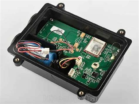
3. Electrolytic Capacitors
3.1 Construction and Materials
Electrolytic capacitors use a liquid or gel electrolyte as one of the electrodes, with a thin oxide layer acting as the dielectric. The two main types are:
- Aluminum Electrolytic Capacitors: Most common, moderate cost.
- Tantalum Electrolytic Capacitors: Higher performance, more expensive.
3.2 Key Characteristics
- High Capacitance (µF to Farads): Suitable for bulk energy storage.
- Polarized: Must be connected with correct polarity to avoid failure.
- Higher ESR: Less efficient at high frequencies.
- Limited Lifespan: Electrolyte dries out over time.
- Voltage Ratings: Typically higher than ceramics (up to hundreds of volts).
3.3 Advantages
- High Capacitance-to-Volume Ratio: Best for energy storage.
- Cost-Effective for Large Values: Cheaper than ceramics for high capacitance.
- Good for Low-Frequency Filtering: Power supply smoothing.
3.4 Disadvantages
- Polarity Sensitivity: Incorrect connection can cause failure.
- Limited Lifespan: Degrades with temperature and time.
- Higher ESR: Not ideal for high-frequency applications.
- Leakage Current: Higher than ceramic capacitors.
3.5 Common Applications
- Power supply filtering (smoothing rectified AC).
- Audio coupling (low-frequency signal passing).
- Energy storage (flash circuits, motor drivers).
- Voltage regulation (in conjunction with regulators).
4. Comparative Analysis
4.1 Performance in Different Scenarios
| Feature | Ceramic Capacitor | Electrolytic Capacitor |
|---|---|---|
| Capacitance Range | pF to µF (limited) | µF to F (high) |
| ESR | Very Low | Moderate to High |
| Frequency Response | Excellent (GHz range) | Poor (best below kHz) |
| Polarity | Non-Polarized | Polarized |
| Lifespan | Very Long | Limited (~10 years) |
| Temperature Stability | Good (C0G) to Poor (Y5V) | Moderate |
| Cost | Low (for small values) | Moderate |
4.2 When to Use Which?
- Use Ceramic Capacitors When:
- High-frequency decoupling is needed (digital ICs).
- Space is constrained (SMD designs).
- Long-term reliability is critical.
- Use Electrolytic Capacitors When:
- High capacitance is required (power supply filtering).
- Cost-effective bulk storage is needed.
- Low-frequency applications (audio, DC smoothing).

5. Emerging Trends and Hybrid Solutions
Modern PCB designs often combine both types for optimal performance:
- Combined Decoupling: Ceramics for high-frequency noise, electrolytics for bulk storage.
- Polymer Electrolytics: Improved ESR and lifespan over traditional electrolytics.
- Advanced MLCCs: Higher capacitance ceramics reducing reliance on electrolytics.
6. Conclusion
Ceramic and electrolytic capacitors serve distinct yet complementary roles in PCB technology. Ceramic capacitors excel in high-frequency, compact applications, while electrolytic capacitors provide high capacitance for power-related functions. Understanding their differences allows engineers to optimize circuit performance, reliability, and cost. Future advancements may further blur the lines between these technologies, but for now, their combined use remains essential in modern electronics.