Reasons for Poor PCB Soldering and How to Avoid Them
Introduction
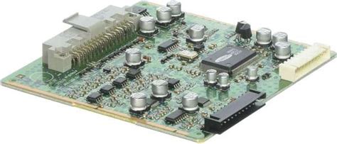
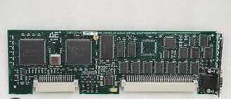
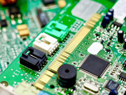
Printed Circuit Board (PCB) soldering is a critical process in electronics manufacturing, ensuring reliable electrical connections between components and the board. However, poor soldering can lead to various issues, including weak joints, short circuits, and complete device failure. Understanding the root causes of poor soldering is essential for improving manufacturing quality and product reliability. This article explores the primary reasons for poor PCB soldering, including material issues, process errors, environmental factors, and human mistakes, along with potential solutions.
1. Poor Quality Solder Materials
The quality of solder materials significantly impacts soldering performance. Common issues include:
a. Low-Quality Solder Alloy
- Using solder with incorrect composition (e.g., wrong tin-lead ratio or contaminated alloys) leads to weak joints.
- Impurities in solder (e.g., oxidation, dirt, or flux residues) reduce wettability and conductivity.
b. Expired or Improperly Stored Flux
- Flux degrades over time, losing its ability to remove oxides and improve solder flow.
- Exposure to moisture or high temperatures can render flux ineffective.
c. Inadequate Solder Paste
- Poorly mixed or expired solder paste results in inconsistent soldering.
- Incorrect viscosity can cause poor deposition during stencil printing.
Solution:
- Use high-quality, industry-standard solder alloys (e.g., SAC305 for lead-free applications).
- Store solder paste and flux in temperature-controlled environments.
- Regularly check solder material expiration dates and mixing procedures.
2. Incorrect Soldering Temperature
Temperature control is crucial for proper solder joint formation.
a. Insufficient Heat
- Cold joints occur when the solder does not melt completely, leading to weak, brittle connections.
- Common in hand soldering with low-wattage irons or improper reflow oven settings.
b. Excessive Heat
- Overheating can damage components, warp PCBs, or burn flux before it cleans the surface.
- Excessive temperatures may also cause solder splatter or tombstoning (component lifting).
Solution:
- Follow manufacturer-recommended temperature profiles for reflow and wave soldering.
- Use a calibrated soldering iron with adjustable temperature settings.
- Monitor oven temperatures and thermal profiles regularly.
3. Poor PCB Design and Manufacturing Defects
Flaws in PCB design or fabrication contribute to soldering problems.
a. Incorrect Pad Design
- Pads that are too small or too large affect solder joint strength.
- Poorly spaced pads lead to bridging (unintended solder connections).
b. Poor Surface Finish
- Oxidation or contamination on copper pads prevents proper solder adhesion.
- Inconsistent surface finishes (e.g., HASL, ENIG, OSP) impact solderability.
c. Warped or Misaligned Boards
- Warping due to heat or mechanical stress causes uneven solder distribution.
- Misaligned stencils result in incorrect solder paste application.
Solution:
- Follow IPC standards for pad size and spacing.
- Use appropriate surface finishes based on application requirements.
- Inspect PCBs for warping before assembly.
4. Improper Soldering Techniques
Human errors and incorrect techniques are common in manual soldering.
a. Inadequate Flux Application
- Too little flux leads to oxidation and poor wetting.
- Too much flux leaves corrosive residues that require cleaning.
b. Incorrect Soldering Iron Handling
- Applying too much pressure damages pads and traces.
- Holding the iron too long on joints causes overheating.
c. Poor Solder Joint Formation
- Insufficient solder results in weak connections.
- Excessive solder causes bridging and short circuits.
Solution:
- Train operators in proper soldering techniques (e.g., drag soldering, rework methods).
- Use automated soldering where possible to reduce human error.
- Implement quality checks for flux application and joint integrity.
5. Contamination and Oxidation
Dirt, moisture, and oxidation prevent proper solder bonding.
a. Dirty or Oxidized PCB Surfaces
- Dust, oils, or oxidation layers inhibit solder adhesion.
- Moisture absorption (especially in hygroscopic components) causes “popcorning” during reflow.
b. Contaminated Solder Tips
- Oxidized or dirty soldering iron tips reduce heat transfer efficiency.
Solution:
- Clean PCBs with isopropyl alcohol before soldering.
- Store PCBs in moisture-controlled environments (use dry cabinets if necessary).
- Regularly clean and tin soldering iron tips.
6. Component-Related Issues
Faulty or incompatible components contribute to soldering defects.
a. Poor Component Solderability
- Oxidation on component leads prevents proper wetting.
- Components with mismatched thermal properties may not solder correctly.
b. Incorrect Component Placement
- Misaligned parts lead to skewed or open solder joints.
- Tombstoning occurs when one end of a component lifts due to uneven heating.
Solution:
- Inspect components for oxidation before assembly.
- Ensure proper thermal profiling for different component types.
- Use pick-and-place machines for accurate component positioning.
7. Environmental Factors
External conditions affect soldering quality.
a. Humidity and Moisture
- High humidity causes solder paste to absorb moisture, leading to splattering.
- Moisture-sensitive components may crack during reflow (popcorning effect).
b. Static Electricity
- Electrostatic discharge (ESD) can damage sensitive components during handling.
Solution:
- Control humidity levels in the assembly area (ideal range: 30-50% RH).
- Use ESD-safe workstations and grounding straps.
Conclusion
Poor PCB soldering results from multiple factors, including material quality, temperature control, PCB design, soldering techniques, contamination, component issues, and environmental conditions. Addressing these problems requires a combination of proper material selection, process optimization, operator training, and environmental controls. By implementing best practices and rigorous quality checks, manufacturers can significantly reduce soldering defects, improving PCB reliability and product performance.
Investing in high-quality materials, automated soldering equipment, and continuous training will help minimize soldering failures, ensuring robust and long-lasting electronic assemblies.