
Rigid-flex circuits and Flexible pcb technical engineering guide
Flexible rigid-flex circuits are a type of printed circuit board (PCB) that combines both flexible and rigid materials to create a circuit board that can bend and flex while still maintaining its structural integrity.
This type of circuit board is commonly used in applications where space is limited or where the circuit board needs to be able to bend or flex to fit into a specific shape or form.
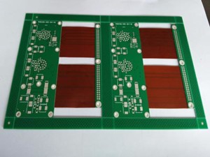
Design considerations:
1. Layer stack-up:
The layer stack-up is an important consideration when designing flexible rigid-flex circuits.
The stack-up should be designed to minimize stress on the flexible portions of the board.
2. Trace width and spacing:
The trace width and spacing should be designed to accommodate the bending and flexing of the board without causing any damage to the traces.
3. Material selection:
The materials used in flexible rigid-flex circuits should be selected based on their ability to withstand bending and flexing without cracking or breaking.
4. Component placement:
Component placement should be carefully considered to ensure that components are not placed in areas that will be subject to excessive bending or flexing.
Manufacturing considerations:
1. Material handling:
The handling of materials during the manufacturing process is critical to the success of flexible rigid-flex circuits.
The materials used in these circuits are delicate and can be easily damaged if not handled properly.
2. Lamination:
The lamination process is critical to the success of flexible rigid-flex circuits.
The lamination process should be carefully controlled to ensure that the layers are properly bonded together.
3. Drilling:
Drilling is another critical process in the manufacturing of flexible rigid-flex circuits.
The drilling process should be carefully controlled to ensure that the holes are drilled in the correct locations and that the holes do not damage the flexible portions of the board.
4. Plating:
Plating is used to add a layer of metal to the surface of the board.
The plating process should be carefully controlled to ensure that the plating is applied evenly and does not damage the flexible portions of the board.
Applications:
Flexible rigid-flex circuits are commonly used in applications where space is limited or where the circuit board needs to be able to bend or flex to fit into a specific shape or form. Some common applications include:
1. Medical devices:
Flexible rigid-flex circuits are commonly used in medical devices where the circuit board needs to be able to bend or flex to fit into the body.
2. Aerospace:
Flexible rigid-flex circuits are commonly used in aerospace applications where space is limited and the circuit board needs to be able to bend or flex to fit into a specific shape or form.
3. Consumer electronics:
Flexible rigid-flex circuits are commonly used in consumer electronics where space is limited and the circuit board needs to be able to bend or flex to fit into a specific shape or form.
4. Automotive:
Flexible rigid-flex circuits are commonly used in automotive applications where the circuit board needs to be able to bend or flex to fit into a specific shape or form.
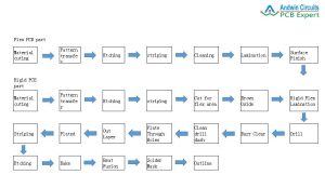
rigid to flex pcb
A rigid to flex PCB is a type of printed circuit board that combines the benefits of both rigid and flexible PCBs.
It consists of a rigid PCB section that is connected to a flexible PCB section through a connector or a hinge.
This allows the PCB to bend or flex in certain areas while maintaining the rigidity and stability of the rest of the board.
Rigid to flex PCBs are commonly used in applications where space is limited or where the PCB needs to conform to a specific shape or contour.
They are also used in applications where the PCB needs to be able to withstand repeated bending or flexing without breaking or damaging the components.
Some common applications of rigid to flex PCBs include medical devices, aerospace and defense systems, automotive electronics, and consumer electronics. They offer several advantages over traditional rigid or flexible PCBs, including improved reliability,
reduced assembly time and cost, and increased design flexibility.
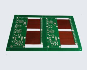
rigid to flex pcb process
The process for manufacturing a rigid to flex PCB involves several steps, including:
1. Design:
The first step is to design the PCB layout using specialized software.
The design must take into account the rigid and flexible sections of the board, as well as the connectors or hinges that will be used to join them.
2. Material selection:
The materials used for the rigid and flexible sections of the board must be carefully chosen to ensure compatibility and reliability.
Common materials include FR-4 for the rigid section and polyimide for the flexible section.
3. Fabrication:
The rigid and flexible sections of the board are fabricated separately using standard PCB manufacturing processes.
This includes drilling, plating, and etching.
4. Assembly:
The rigid and flexible sections of the board are then assembled together using a connector or hinge.
This requires precise alignment and careful handling to avoid damaging the components.
5. Testing:
The finished PCB is then tested to ensure it meets the required specifications and functions as intended.
Overall, the process for manufacturing a rigid to flex PCB is similar to that of a traditional PCB,
but requires additional steps and specialized expertise to ensure the rigid and flexible sections are properly integrated.