
Skip to content
Andwin Circuits
  • Home
  • ProductsExpand
    • HDI multilayer PCB
    • Rigid Flex PCB
    • Flex pcb
    • Special PCBExpand
      • High Frequency PCBExpand
        • Rogers RO4350B PCB
        • Rogers RO4003 pcb
        • Rogers RO3003 PCB
        • Rogers 5880 PCB
        • DICLAD 527 PCB
        • Taconic TLX series
        • Taconic TLX-8 RF PCB
        • Taconic TLX-9 RF PCB
      • High speed pcbExpand
        • Megtron 6 High Speed PCB
        • TU-872 SLK Sp High Speed
      • High TG PCBExpand
        • SHENGYI SH260 PCB
        • ISOLA 370HR PCB
        • ISOLA IS410 PCB
        • ISOLA IS420 PCB
      • Heavy copper PCB
      • Copper coin pcb
      • Copper inlay PCB
    • Metal Core PCBExpand
      • Copper core pcb
      • Aluminum PCB
      • 2 Layers Aluminum PCB
      • Direct thermal MCPCB
      • 2 Layers Direct Thermal
    • Ceramic PCBExpand
      • DPC ceramic PCB
      • DBC ceramic PCB
      • Thick film Ceramic PCB
      • Al2O3 Alumina PCB
      • AIN ALN ceramic PCB
      • IGBT Ceramic PCB
  • ServiceExpand
    • PCB Assembly
    • Quick turn PCB assembly
    • PCBA conformal coating
  • IndustryExpand
    • Telecommunication
    • IoT and Wireless
    • Industrial Control
    • Thermal management
    • Power and Energy
    • IC test board
    • Automative
    • Medical
  • CapabilityExpand
    • Rigid PCB
    • Rigid flex PCB
    • Metal core PCB
    • PCB Assembly
  • TechnologyExpand
    • Blogs
    • Via in pad
    • PCB E-test
    • PCB stack up
    • MCPCB panelization
    • Controlled impedance PCB
  • AboutExpand
    • About us
    • Certification
    • Factory Tour
  • Contact
Andwin Circuits
Home / Blogs / Rigid flex pcb design guidelines

Rigid flex pcb design guidelines

ByIvy May 24, 2023June 19, 2024

Rigid flex pcb design Guidelines

A rigid-flex PCB is a type of printed circuit board that combines both rigid and flexible PCBs. It consists of multiple layers of rigid and flexible materials laminated together to create a single board.

The rigid sections provide stability and support for components, while the flexible sections allow the board to bend and twist to fit into tight spaces or conform to a specific shape. Rigid-flex PCBs are commonly used in applications where space is limited, such as in medical devices, aerospace, and military equipment.

They offer improved reliability, reduced assembly time, and increased design flexibility compared to traditional rigid PCBs.
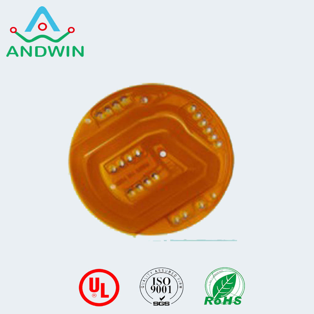
Rigid flex pcb design guidelines

1. Material Selection: Choose the right materials for your design. The most common materials used for rigid-flex PCBs are FR-4 and polyimide.

Make sure to select the right materials based on your design requirements.

2. Bend Radius: The bend radius is the minimum radius that a flex circuit can bend without causing damage.

The bend radius should be carefully considered during the design phase to avoid any damage to the circuit.

3. Trace Width and Spacing: The trace width and spacing should be carefully considered to ensure that the circuit can handle the required current and voltage.

The spacing should be increased in areas where the circuit will be bent.

4. Via Placement: The via placement should be carefully considered to ensure that the circuit can handle the required current and voltage.

Vias should be placed away from areas where the circuit will be bent.
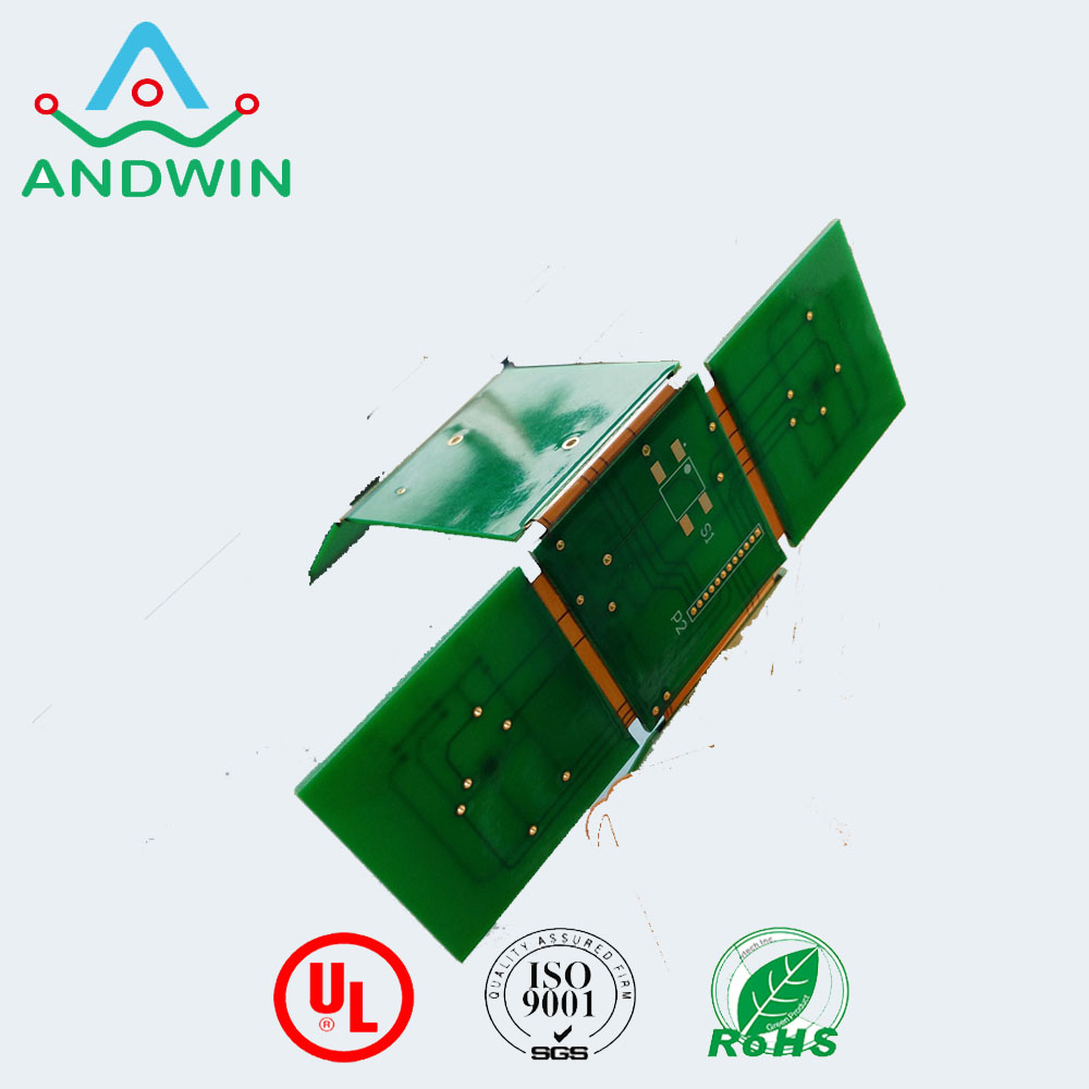
GET IN TOUCH!

5. Component Placement: Component placement should be carefully considered to ensure that the components are placed in areas where the circuit will not be bent. Components should be placed in areas where they will not interfere with the bending of the circuit.

6. Stiffeners: Stiffeners are used to provide additional support to the circuit in areas where it will be bent.

Stiffeners should be carefully designed and placed to ensure that they provide the required support.

7. Testing: Testing should be performed on the circuit to ensure that it meets the required specifications.

Testing should be performed on the circuit before and after bending to ensure that there is no damage to the circuit.

8. Manufacturing: Manufacturing should be carefully considered to ensure that the circuit is manufactured to the required specifications.

The manufacturing process should be carefully monitored to ensure that there is no damage to the circuit during the manufacturing process.
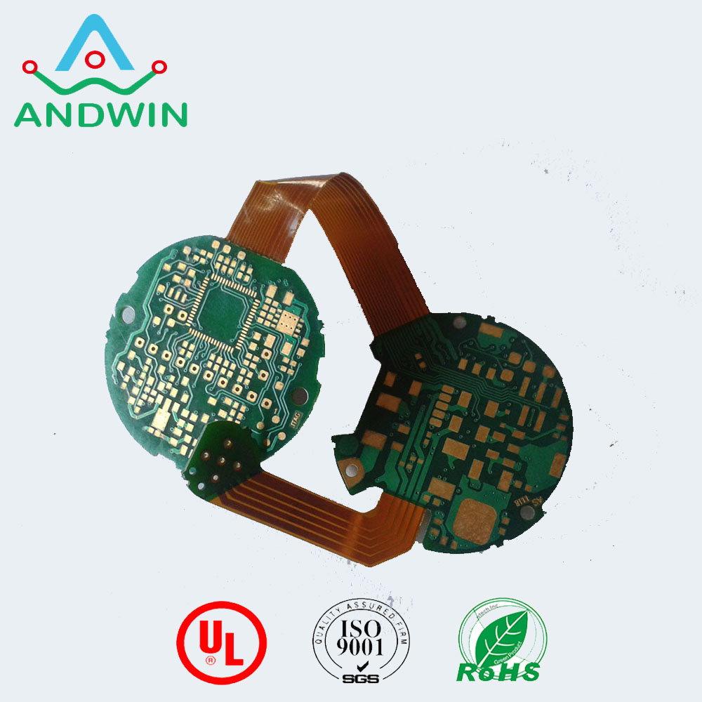
Material Considerations for Rigid-Flex PCB Design

Talk to your manufacturer to ensure you select the right material for your rigid-flex design

You’ll want to consult your PCB manufacturer before starting a design. Depending on whether the PCB is meant for dynamic bend or stable bend, the choice of copper type, the number of layers, bend radius, and coverlays may differ.

A dynamic bend rigid-flex PCB is installed in an environment where it will constantly be subjected to bending. Therefore, it is recommended to use no more than 2 layers and ensure that the bending radius is at least 100 times the material thickness.

Meanwhile, it’s possible to have up to 10 to 20 layers for a rigid-flex PCB that’s meant for stable-bend installations. It is not subjected to repeated bending force and that means a smaller bending radius of about 10 times its material thickness is also possible.

GET IN TOUCH!

Post navigation

Previous Previous
Ceramic PCB, Ceramic PCB Suppliers and Manufacturers in China
NextContinue
Flex rigid pcb design rules-Andwin

Search

Search

Products

  • HDI Multilayer PCB
  • Rigid Flex PCB
  • Flex pcb
  • High Frequency PCB
  • High speed pcb
  • Heavy copper PCB
  • Metal Core PCB
  • Ceramic PCB

Address

Andwin Circuits Co.,Limited
Email: sales@andwinpcb.com
Tel: +86 755 2832 9394
Fax:+86 755 2992  6717
ADD:1-2F-1217,HouDeQun Industrial park,
NanTing RD NO.56,ShaJing,BaoAn,Shenzhen 518104,GuangDong,China

Products

  • HDI Multilayer PCB
  • Rigid Flex PCB
  • Flex pcb
  • High Frequency PCB
  • High speed pcb
  • Heavy copper PCB
  • Metal Core PCB
  • Ceramic PCB

Technology

  • Blogs
  • Via in pad
  • PCB E-test
  • PCB stack up
  • Metal core PCB panelization
  • Controlled impedance PCB

CERTIFICATION

Certification >>


Copyright© 2003 - 2026 Andwin | All Rights Reserved | Powered by Andwin

Scroll to top
  • Home
  • Products
    • HDI multilayer PCB
    • Rigid Flex PCB
    • Flex pcb
    • Special PCB
      • High Frequency PCB
        • Rogers RO4350B PCB
        • Rogers RO4003 pcb
        • Rogers RO3003 PCB
        • Rogers 5880 PCB
        • DICLAD 527 PCB
        • Taconic TLX series
        • Taconic TLX-8 RF PCB
        • Taconic TLX-9 RF PCB
      • High speed pcb
        • Megtron 6 High Speed PCB
        • TU-872 SLK Sp High Speed
      • High TG PCB
        • SHENGYI SH260 PCB
        • ISOLA 370HR PCB
        • ISOLA IS410 PCB
        • ISOLA IS420 PCB
      • Heavy copper PCB
      • Copper coin pcb
      • Copper inlay PCB
    • Metal Core PCB
      • Copper core pcb
      • Aluminum PCB
      • 2 Layers Aluminum PCB
      • Direct thermal MCPCB
      • 2 Layers Direct Thermal
    • Ceramic PCB
      • DPC ceramic PCB
      • DBC ceramic PCB
      • Thick film Ceramic PCB
      • Al2O3 Alumina PCB
      • AIN ALN ceramic PCB
      • IGBT Ceramic PCB
  • Service
    • PCB Assembly
    • Quick turn PCB assembly
    • PCBA conformal coating
  • Industry
    • Telecommunication
    • IoT and Wireless
    • Industrial Control
    • Thermal management
    • Power and Energy
    • IC test board
    • Automative
    • Medical
  • Capability
    • Rigid PCB
    • Rigid flex PCB
    • Metal core PCB
    • PCB Assembly
  • Technology
    • Blogs
    • Via in pad
    • PCB E-test
    • PCB stack up
    • MCPCB panelization
    • Controlled impedance PCB
  • About
    • About us
    • Certification
    • Factory Tour
  • Contact
Search