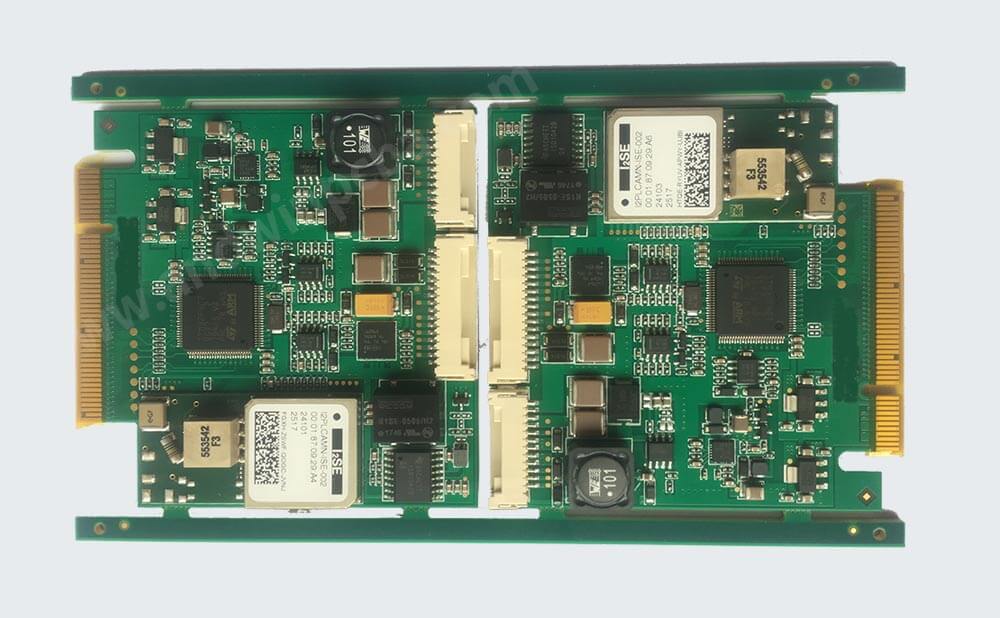
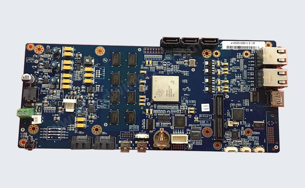
Rogers PCB: Rogers PCB material in stock fast delivery
What is Rogers PCB?
Rogers PCB material is a company that manufactures the laminate materials that are used to make PCB boards.
Most PCB boards are made of a material known as FR4 (Flame Retardant level 4),
Which is a glass fiber / epoxy composite,
With copper foil laminated on one or both sides.
Rogers PCB hydrocarbon ceramic laminates are designed to offer superior high frequency
performance and low cost circuit fabrication.
The result is a low loss material,
which can be fabricated using standard epoxy/glass (FR-4) processes offered at competitive
prices.
They are better known for cores with better high frequency properties, such as PTFE (Teflon).
They are more expensive than fiber glass, but are less lossy at high frequencies.
This makes them be good for Radio Frequency PCB boards.
Also,Rogers PCB is a type of high-frequency board produced by Rogers.
It is different from the conventional PCB board—epoxy resin (FR4).
It has no glass fiber in the middle and uses a ceramic base as the high-frequency material.
Rogers PCB has superior dielectric constant and temperature stability.
Its dielectric constant thermal expansion coefficient is very consistent with copper foil,
which can be used to improve the deficiencies of PTFE substrates.
It is very suitable for high-speed electronic design,
commercial microwave, and radio frequency applications.
It’s low water absorption is ideal for high-humidity applications,
Providing customers in the high-frequency PCB industry with the highest quality materials and related resources,
which fundamentally enhance product quality.

Rogers PCB types
3001 Bonding Film (Thermoplastic Chloro-fluorocopolymer)
RO3000® series High-Frequency Laminates (PTFE/Ceramic)
RO3035® series High-Frequency Laminates (PTFE/Ceramic)
RO3200® series High-Frequency Laminates (PTFE/Ceramic)
RO4000® High-Frequency Laminate with TICER Foil
RO4000® laminates datasheet
Fabrication guidelines: RO4003C, RO4350B
RO4400® prepreg :RO4450B, RO4450F
RO4500® Antenna Grade Laminates for High Volume Applications
RT/duroid® 5870/5880 Glass Microfiber Reinforced PTFE Composites
RT/duroid® 6002
RT/duroid® 6202
RT/duroid® 6202PR
RT/duroid® 6006/6010
TMM Thermoset:
TMM3, TMM4, TMM6, TMM10, TMM10i
ULTRALAM 2000
ULTRALAM 3000 LCP : ULTRALAM 3850
ULTRALAM 3000 LCP Prepreg: ULTRALAM 3908
R/flex CRYSTAL 7500 Laminates and Coverlayers
R/flex CRYSTAL 7700 Laminates and Coverlayers
R/flex JADE A coverfilm
R/flex JADE A laminates
R/flex JADE J coverfilm
R/flex JADE J laminate
LONGLITE™ AND R/flex® Flexible Circuit Materials – Thin Dielectrics
LONGLITE™ Flex 200 Adhesiveless Materials
LONGLITE™ Flex 300 Adhesiveless Series
R/flex® 2001 Laminates and Coverfilms
R/flex® 2005 Laminates and Coverfilms
R/flex® 1000 Circuit Materials for Long-life Dynamic Flexing
R/flex® 1100 Circuit Materials – High-Temperature Laminates
R/flex® 1500 Assembly Adhesive
8080 Liquid Photoimageable Covercoat
8080 Liquid Photoimageable Covercoat: LP11
8080 Liquid Photoimageable Covercoat: LP2

Features of Rogers PCB
The basic difference between Rogers PCB and ordinary PCB states for the high-frequency PCB used in heavy industrial purposes or applications.
The quality outperforms than the general PCB and it is trusted by many people to use in complex and crucial purposes.
The distinctive features that have made it extra-ordinary include:
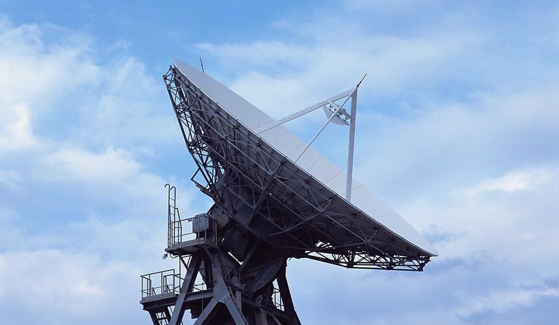
The application where Rogers PCBs can be used for microwave point to point,
RF identification tags, automotive radar and sensors,and power amplifiers
It is composed with woven glass reinforced hydrocarbon
High-resolution electrical performance has close interaction to PTEE
A thin layer of conductive materials are used in PCBs to give it strength and power
Raw materials used in Rogers PCB:
There is a number of materials used in Rogers PCB
But the primary materials are the following:
Laminated materials composed of woven glass-reinforced epoxy laminates
Cross piled woven glass-reinforced laminates
PTEE ceramic laminates
Woven glass-reinforced modified epoxy laminates
Woven glass reinforced PTFE antenna grade laminates
Cross-plied woven glass reinforced PTFE
Woven glass-reinforced modified epoxy IMS
Hydrocarbon/ ceramic/ woven glass UL 94 V-0 Laminates
Hydrocarbon/ ceramic / woven Glass
PTFE ceramic
Filled PTFE composite
PTFE random glass fiber
Several models of metal cladding accessible in the following foil type:
Rolled
Electrodeposited
Electrodeposited Reverse Treated
Resistive foil

Why choose Rogers PCB material?
FR-4 material provides the fundamental standard for PCB substrates,
keeping a widely effective balance between cost, durability,
Performance, manufacturability, as well as electrical properties.
However,as performance and electrical properties plays an important role in your designs.
Rogers PCB materials have the advantages as follows:
1- Effective-cost PCB fabrication
2- Lower dielectric loss
3- Better thermal management
4- Low electrical signal loss
5- Wide range of Dk (dielectric constant) values (2.55-10.2)
6- Improve impedance control
7- Low outgassing for space applications

What is difference between rogers and FR4 PCB?
1. Composition:
Rogers PCB is a high-performance material made of ceramics and glass fibers,
While FR4 is a composite material made of woven glass fabric and epoxy resin.
2. Dielectric Constant:
Rogers has a lower dielectric constant than FR4,
Which means it can transmit signals faster and with less loss.
3. Loss Tangent:
Rogers PCB has a lower loss tangent than FR4,
Which means it can maintain signal integrity over longer distances.
4. Thermal Conductivity:
Rogers PCB has a higher thermal conductivity than FR4,
Which means it can dissipate heat more efficiently.
5. Cost:
Rogers PCB is more expensive than FR4, which makes it less commonly used in consumer electronics.
In summary, Rogers PCB is a high-performance material that offers better signal integrity and thermal management,
But it is more expensive than FR4.
FR4 is a more affordable and widely used material that is suitable for most consumer electronics applications.
Benefits of Rogers PCB
There are several reasons for the increasing popularity of Rogers PCB.
The best quality and better usage criteria and features are the most obvious reasons because the other alternatives can barely supportive of such issues.
This high-frequency Rogers PCB has several benefits.
1- Lower dielectric failure
2- Low moisture absorption
3- Advanced impedance control
4- Suitable for RF circuit boards
5- Better management for thermal energy
6- A wide array of dielectric constant values
7- High quality ensures low electrical signal loss
8- Lower outgassing is suitable for space applications
9- Extremely reliable and available for use in major industries
10- High frequency assures the suitability to use in mobile networking and aerospace

Rogers PCB application:
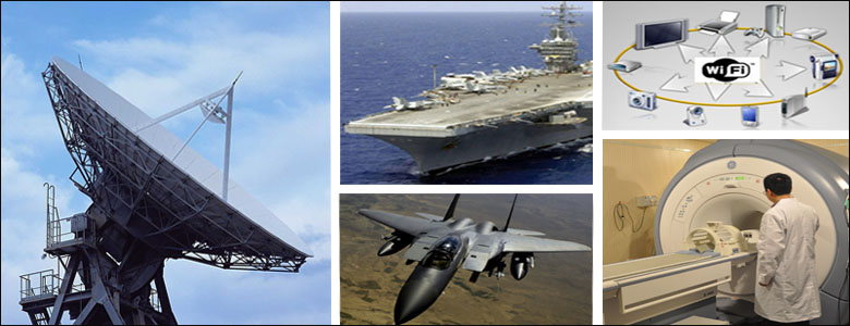
The application where Rogers PCBs can be used for microwave point to point,
RF identification tags, automotive radar and sensors, and power amplifiers
It is composed with woven glass reinforced hydrocarbon,
High-resolution electrical performance has close interaction to PTEE.
A thin layer of conductive materials are used in PCBs to give it strength and power.
Rogers PCBs are highly effective to use in:
- Defense
- Military
- Wireless
- Telecommunication
- Automotive industries
Also,there are more examples of other applications,
More application be used by Rogers PCB:
- Cellular Base Station Antennas
- Phased Array Radar Systems
- Power Amplifiers
- Automotive Radar and Sensors
- RF identification (RFID) Tags
- Direct Broadcast Satellites
- Active Safety
- Antenna Systems
- Backhaul Radios
- Direct Broadcast Satellites
- Carrier-Grade Wi-Fi / Licensed Assisted Access
- IP Infrastructure
- Small Cells / DAS
- Test & Measurement
Rogers PCB design guide line
1. Choose the right substrate:
Rogers PCBs are made of a variety of substrates with different dielectric constants and loss tangents.
Choose the substrate that best suits your application.
2. Keep the trace width and spacing in mind:
The trace width and spacing should be designed according to the required impedance and the thickness of the substrate.
3. Use a ground plane:
A ground plane helps to reduce electromagnetic interference (EMI) and crosstalk.
It also helps to provide a stable reference plane for signal routing.
4. Avoid sharp corners:
Sharp corners can cause reflections and impedance mismatches.
Use rounded corners instead.
5. Use vias carefully:
Vias can cause impedance changes and signal reflections.
Use them sparingly and place them carefully.
6. Use proper termination techniques:
Proper termination techniques such as series termination or
Parallel termination can help to reduce reflections and improve signal integrity.
7. Test the design:
Test the PCB design using a network analyzer or
Other appropriate testing equipment to ensure that it meets the required specifications.
These are just general guidelines.
For more detailed information,
refer to the specific datasheet of the Rogers substrate you are using and consult with a PCB design expert.
Other PCB products, you may interesting


