Safety Certification Standards for BMS Hardware-Software Integrated Boards in Electric Vehicles
The electric vehicle market is pushing battery management systems into increasingly complex territory. In our automotive electronics practice, we’ve seen BMS board failures traced back to inadequate certification planning during the design phase. When hardware and software integration goes wrong at the board level, the consequences range from reduced battery life to thermal runaway incidents.
This guide walks through the certification landscape that determines whether your BMS board meets automotive safety requirements—and more importantly, how to design for compliance from day one rather than retrofitting later.
Understanding BMS Hardware-Software Integration Requirements
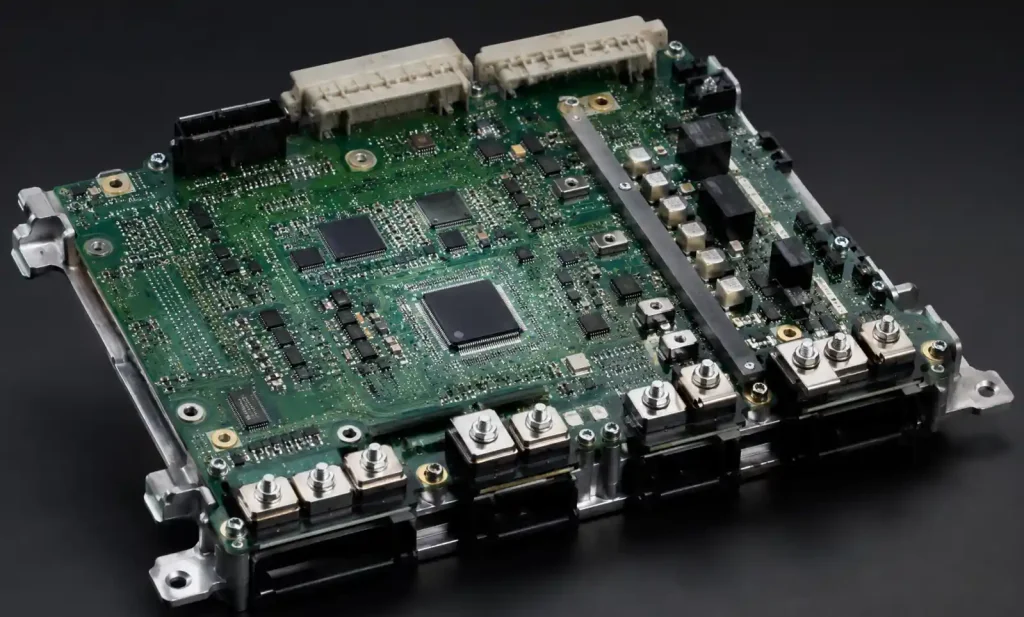
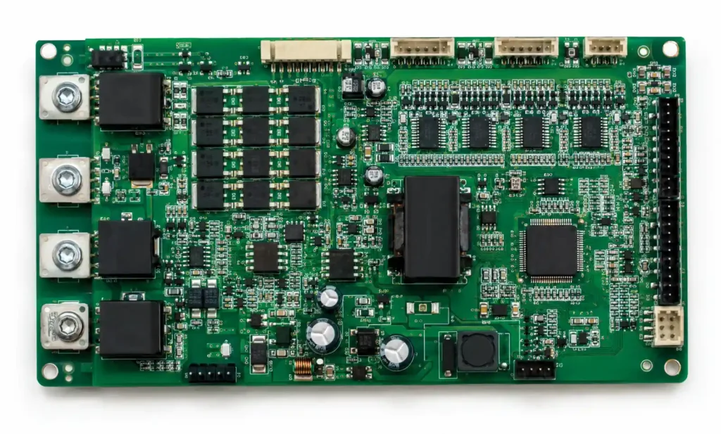
Battery management systems in electric vehicles handle critical safety functions: cell monitoring, thermal management, state-of-charge calculation, and protection against overcharge or deep discharge. The hardware-software integrated board is where these functions physically converge—microcontrollers running safety algorithms, analog front-ends measuring cell voltages, and power stages controlling contactors.
The integration challenge isn’t just electrical. When we design BMS boards for ASIL-C or ASIL-D applications, the hardware must support software safety mechanisms like memory protection, watchdog monitoring, and redundant processing paths. A board that works perfectly in functional testing can fail certification if it doesn’t provide the hardware hooks the safety software requires.
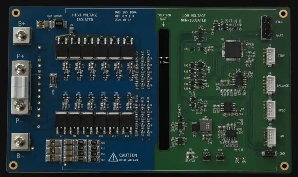
In practice, this means BMS boards need isolated power domains for safety-critical functions, hardware-enforced memory boundaries, and physical separation between high-voltage and low-voltage circuits that goes beyond standard PCB design rules.
Core Safety Certification Standards for BMS Boards
Multiple certification standards apply to BMS hardware, each targeting different aspects of safety and quality. The table below compares the primary standards:
| Standard | Primary Focus | Key Requirements for BMS Boards | Typical ASIL/SIL Level |
|---|---|---|---|
| ISO 26262 | Functional safety for road vehicles | Hardware fault metrics, safety architecture, diagnostic coverage | ASIL-B to ASIL-D |
| IEC 61508 | General functional safety (often referenced for components) | Hardware failure analysis, systematic capability | SIL 2 to SIL 3 |
| UL 2580 | Battery safety for electric vehicles | Electrical safety, thermal management, fault protection | N/A (pass/fail) |
| UN ECE R100 | Electric powertrain safety (Europe) | High-voltage safety, insulation resistance, protection against direct contact | N/A (regulatory) |
| GB/T 31467 | BMS technical requirements (China) | Communication protocols, SOC accuracy, protection functions | N/A (mandatory) |
ISO 26262 dominates the automotive space. For BMS boards, this typically means achieving ASIL-C or ASIL-D classification depending on the vehicle architecture. A centralized BMS controlling a 100kWh pack in a passenger vehicle will face ASIL-D requirements; a modular BMS with redundant safety layers might target ASIL-C per module.
The critical insight: these standards aren’t checklists applied after design completion. They define architectural decisions—like whether you need dual-channel voltage sensing or hardware-enforced communication redundancy—that must be baked into the board from initial schematic capture.
ISO 26262 Functional Safety Implementation
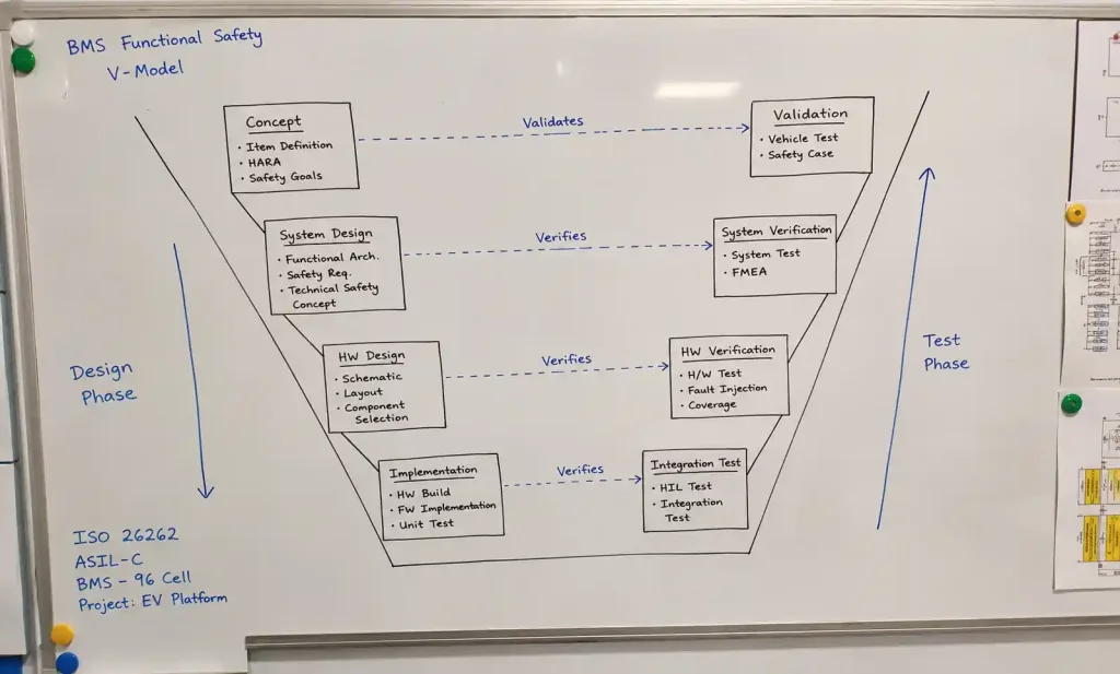
ISO 26262 structures functional safety into a V-model development process. For BMS hardware-software integrated boards, this creates specific obligations at each phase.
During concept phase, you define the safety goals derived from hazard analysis. A typical BMS safety goal: “Prevent battery overcharge that could lead to thermal runaway” (ASIL-D). This cascades down to functional safety requirements like “Detect cell overvoltage within 100ms” and technical safety requirements like “Hardware shall provide dual independent voltage measurement channels with <10mV discrepancy detection.”
The hardware design phase demands several specific artifacts for certification:
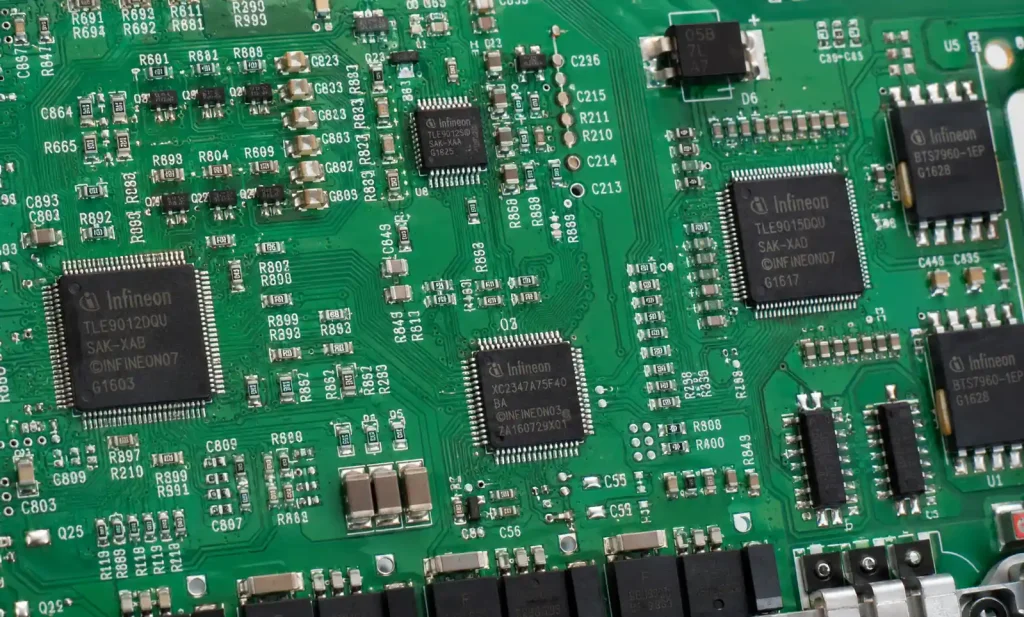
Hardware architectural metrics must meet target values. For ASIL-D, single-point fault metric (SPFM) must exceed 99%, and latent fault metric (LFM) must exceed 90%. This drives redundancy decisions—for example, using two independent AFE (analog front-end) chips rather than relying on internal diagnostics of a single chip.
In our most recent ASIL-D BMS project, we implemented dual-channel voltage sensing with continuous cross-checking, independent temperature sensors on critical cell monitoring points, and physically separated power supplies for the safety microcontroller. The board cost increased by approximately 18%, but it eliminated multiple single points of failure that would have blocked certification.
Diagnostic coverage is another hard requirement. The hardware must support software diagnostics that detect ≥90% of hardware faults (for ASIL-C) or ≥99% (for ASIL-D). This means adding test points, built-in self-test circuits, and redundant sensing paths that the software can poll to verify hardware integrity.
Hardware-Specific Certification Requirements
Beyond functional safety standards, BMS boards face hardware-level certification requirements that address electrical safety, thermal management, and environmental resilience.
PCB Design Requirements:
Automotive-grade BMS boards typically require IPC Class 3 manufacturing for high-reliability applications. Trace spacing for high-voltage sections must meet creepage and clearance distances per IEC 60664-1—for 400V battery systems, we typically design with ≥4mm clearance between high-voltage and low-voltage domains, even though the standard minimum might be lower. Better safe than re-spinning boards during certification testing.
| Voltage Level | Minimum Creepage | Minimum Clearance | Material Group | Pollution Degree |
|---|---|---|---|---|
| <60V DC | 0.5mm | 0.5mm | IIIa | 2 |
| 60-150V DC | 1.5mm | 1.5mm | IIIa | 2 |
| 150-300V DC | 2.5mm | 2.5mm | IIIa | 2 |
| 300-600V DC | 4.0mm | 4.0mm | IIIa | 2 |
| >600V DC | 5.5mm | 5.5mm | IIIa | 2 |
Thermal management becomes critical for certification. UL 2580 testing includes thermal abuse scenarios where the BMS must detect and respond to thermal runaway initiation. This requires hardware placement that ensures temperature sensors are located at critical thermal nodes, not just convenient PCB positions.
Component Selection:
Safety-critical ICs must carry automotive qualification (AEC-Q100 for integrated circuits, AEC-Q200 for passive components). In practice, this limits your component choices—you can’t just swap in a cheaper ADC during cost reduction if it lacks automotive qualification, because that triggers recertification.
We specify components with operating temperature ranges of -40°C to +125°C for automotive BMS boards, even though the battery pack thermal management typically keeps the BMS between 0°C and 60°C. Certification testing will expose your board to temperature extremes, and marginal components will fail.
Testing and Validation Protocols
Certification requires extensive testing that goes far beyond functional validation. The test protocols for BMS hardware-software integrated boards break into several categories:
Functional Safety Testing:
Hardware fault injection is mandatory for ISO 26262 compliance. Test houses will physically inject faults—shorting signals, interrupting power supplies, forcing communication errors—and verify that the hardware and software detect these faults within the specified diagnostic interval. We’ve seen boards fail certification because the diagnostic software couldn’t detect a specific fault mode that the hardware designer didn’t anticipate during architecture definition.
For ASIL-C/D BMS boards, expect to demonstrate fault detection coverage through hundreds of specific fault injection scenarios. Budget 8-12 weeks for fault injection campaigns at an accredited test lab.
Environmental Testing:
Automotive environmental requirements come from standards like ISO 16750 (electrical and electronic equipment in road vehicles). Your BMS board will face:
- Thermal cycling: -40°C to +85°C with multiple cycles and dwell times
- Vibration testing: 10-2000 Hz, multiple axes, extended duration
- Shock testing: mechanical shock pulses simulating crash scenarios
- Humidity testing: 85% RH at elevated temperature with condensation cycles
- Salt spray: corrosion resistance for underbody locations
In our experience, vibration testing reveals PCB layout weaknesses—inadequately supported connectors, heavy components without mechanical reinforcement, and flex points in the board that accumulate stress. Design review for mechanical stress is just as important as electrical review.
EMC Testing:
Electromagnetic compatibility testing for automotive electronics follows CISPR 25 for emissions and ISO 11452 for immunity. BMS boards must handle conducted and radiated immunity testing at levels that would destroy typical consumer electronics.
For high-voltage BMS boards, expect immunity testing at 200 V/m field strength for radiated immunity, and conducted immunity on power and signal lines that simulates electrical transients from other vehicle systems. Poor grounding architecture or inadequate filtering will show up immediately in EMC testing.
Regional Compliance Variations
Certification requirements vary significantly by market, creating complexity for global BMS deployments.
China Market (GB Standards):
China mandates compliance with GB/T 31467 series for BMS technical requirements and GB 38031 for battery safety. These standards specify communication protocols (typically CAN bus message formats), state-of-charge accuracy requirements (±5% for usable SOC range), and protection function response times.
In practice, Chinese standards emphasize different priorities than ISO 26262. Where ISO 26262 focuses on systematic development process and fault metrics, GB standards specify minimum performance requirements for protection functions. A BMS board can meet one standard but not the other, requiring design modifications for different markets.
European Market (ECE Regulations):
UN ECE R100 governs electric powertrain safety in Europe. For BMS boards, the critical requirements involve high-voltage safety: insulation resistance monitoring, galvanic isolation between high-voltage and low-voltage circuits, and protection against direct contact with live parts.
ECE R100 requires continuous insulation monitoring during vehicle operation, which means the BMS hardware must include insulation monitoring circuits or interfaces to external insulation monitoring devices. This isn’t typically required by ISO 26262, creating an additional hardware requirement for European-market vehicles.
North American Market (UL/SAE Standards):
UL 2580 remains the primary battery safety certification in North America. Unlike ISO 26262’s focus on functional safety process, UL 2580 emphasizes fault testing—what happens when the BMS fails, not how you designed the BMS to prevent failures.
UL 2580 testing includes external short circuit, overcharge, over-discharge, thermal abuse, and mechanical abuse scenarios. The BMS board must demonstrate that it can detect and respond to these scenarios before they create safety hazards. In testing, the failure modes matter as much as the normal operating modes.
Common Certification Pitfalls
After supporting dozens of BMS certification programs, certain failure patterns appear repeatedly:
Inadequate Diagnostic Coverage:
Teams design hardware with good fault tolerance (redundant sensors, dual power supplies) but fail to provide software access to diagnostic information. The hardware can detect faults internally but doesn’t expose fault flags to the safety microcontroller. During certification testing, the fault injection campaign reveals that specific fault modes are undetectable by software, failing the diagnostic coverage requirement.
Solution: Define diagnostic strategy during hardware architecture phase, not during software integration. Every redundant element needs diagnostic visibility to the safety controller.
Insufficient Hardware Independence:
ISO 26262 requires “freedom from interference” between safety elements. We’ve seen BMS designs where the safety microcontroller and application microcontroller share the same power supply regulator, creating a common-cause failure mode. Or where independent voltage sensing channels share the same reference voltage, compromising their independence.
Certification audits will trace signal paths and identify common-cause failures that invalidate claimed independence. The fix requires hardware redesign, not software patches.
Creepage/Clearance Violations:
High-voltage isolation requirements are straightforward in principle but easy to violate in dense PCB layouts. Certification testing measures actual creepage distances on manufactured boards, and violations found during testing require board redesign.
In one recent case, a BMS board passed electrical safety analysis during design review but failed certification testing because component body overhang reduced the effective creepage distance below the required minimum. The components were placed legally per the schematic, but physical component dimensions created a violation that only became apparent in 3D mechanical review.
Thermal Derating Underestimation:
Certification testing occurs at elevated ambient temperatures (typically 85°C). Components that operate comfortably at 25°C may exceed maximum junction temperature at 85°C ambient when mounted on a BMS board inside a battery pack enclosure.
We now perform thermal simulation at worst-case ambient temperature plus internal heating from power dissipation, with component derating applied per automotive standards (typically 80% of absolute maximum ratings for safety-critical components). This catches thermal issues during design rather than during certification testing.
Design-for-Certification Best Practices
Successful BMS certification starts with architectural decisions made before detailed design begins:
Early Safety Architecture Definition:
Engage a functional safety consultant during concept phase, not during validation phase. The safety architecture—which functions carry which ASIL ratings, how redundancy is implemented, where safety boundaries exist—determines hardware architecture. Trying to retrofit safety into a completed hardware design rarely succeeds.
For a recent ASIL-D BMS project, we spent three weeks on safety concept and architecture definition before starting schematic capture. This front-loaded effort eliminated multiple potential redesign cycles later.
Component Selection for Diagnostics:
Choose ICs with built-in diagnostic features that support your ASIL target. Modern battery monitoring ICs include diagnostic features like open-wire detection, internal reference voltage monitoring, and communication integrity checks. These features contribute directly to diagnostic coverage metrics.
In component selection, favor parts with automotive qualification and safety documentation from the manufacturer. IC vendors increasingly provide safety manuals that document failure modes, diagnostic coverage, and safe failure fractions—documentation that directly supports your ISO 26262 safety case.
Modular Safety Architecture:
Partition the BMS board into safety domains with clear interfaces. A typical architecture separates high-voltage power stages, analog sensing circuits, safety controller, and application controller into distinct blocks with defined communication paths and power domains.
This modularity simplifies both design-for-safety and certification testing. Fault injection can target specific blocks, and diagnostic coverage can be analyzed per block rather than trying to reason about the entire board as a monolithic safety element.
Test Access and Observability:
Design test points and diagnostic access into the hardware from the beginning. Certification testing will require visibility into internal signals for fault injection verification. Without test access, you can’t demonstrate diagnostic coverage.
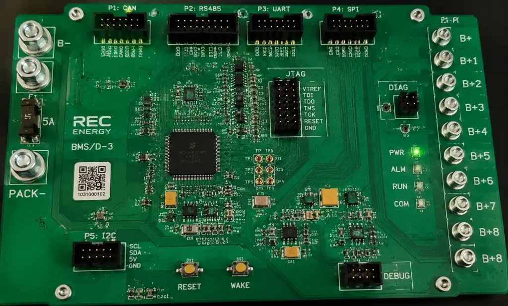
We include JTAG access on safety microcontrollers, test points on critical analog signals, and breakout headers for communication buses. During functional development, these seem like unnecessary overhead. During certification testing, they’re essential.
Documentation Discipline:
ISO 26262 requires traceability from safety goals through functional safety requirements, technical safety requirements, hardware architecture, and hardware implementation. Maintain this traceability in your design tools from day one.
Use requirements management tools that link safety requirements to hardware elements in your schematic and layout. When a certification auditor asks “which hardware components implement technical safety requirement TSR-BMS-42,” you should be able to answer in seconds, not days.
Supplier Quality Management:
For safety-critical BMS boards, component supplier qualification matters. ISO 26262 requires confidence in hardware components, which typically means selecting suppliers with ISO/TS 16949 automotive quality certification and documented quality processes.
In our supply chain qualification process for ASIL-C/D BMS boards, we audit component suppliers for automotive quality processes, require failure mode documentation, and establish traceability for components down to manufacturing lot codes. This creates supply chain overhead but provides the confidence needed for safety certification.
Conclusion
Safety certification for BMS hardware-software integrated boards isn’t a final validation step—it’s an architectural requirement that shapes design from initial concept through production release. The successful projects we’ve supported treat certification requirements as design inputs, not design outputs.The automotive functional safety standards like ISO 26262 drive specific hardware architecture decisions: redundancy strategies, diagnostic coverage implementation, and fault handling mechanisms that must be designed into the board layout and component selection. Regional certification variations add complexity, requiring design flexibility to address market-specific requirements without complete hardware redesign.
Start with safety architecture definition before detailed hardware design. Engage functional safety expertise early. Design for diagnostics and testability from the beginning. And maintain disciplined documentation traceability throughout the development process.When these practices become standard process rather than afterthoughts, BMS board certification changes from an uncertain gauntlet into a predictable validation of designs that were built for safety from day one.