
Skip to content
Andwin Circuits
  • Home
  • ProductsExpand
    • HDI multilayer PCB
    • Rigid Flex PCB
    • Flex pcb
    • Special PCBExpand
      • High Frequency PCBExpand
        • Rogers RO4350B PCB
        • Rogers RO4003 pcb
        • Rogers RO3003 PCB
        • Rogers 5880 PCB
        • DICLAD 527 PCB
        • Taconic TLX series
        • Taconic TLX-8 RF PCB
        • Taconic TLX-9 RF PCB
      • High speed pcbExpand
        • Megtron 6 High Speed PCB
        • TU-872 SLK Sp High Speed
      • High TG PCBExpand
        • SHENGYI SH260 PCB
        • ISOLA 370HR PCB
        • ISOLA IS410 PCB
        • ISOLA IS420 PCB
      • Heavy copper PCB
      • Copper coin pcb
      • Copper inlay PCB
    • Metal Core PCBExpand
      • Copper core pcb
      • Aluminum PCB
      • 2 Layers Aluminum PCB
      • Direct thermal MCPCB
      • 2 Layers Direct Thermal
    • Ceramic PCBExpand
      • DPC ceramic PCB
      • DBC ceramic PCB
      • Thick film Ceramic PCB
      • Al2O3 Alumina PCB
      • AIN ALN ceramic PCB
      • IGBT Ceramic PCB
  • ServiceExpand
    • PCB Assembly
    • Quick turn PCB assembly
    • PCBA conformal coating
  • IndustryExpand
    • Telecommunication
    • IoT and Wireless
    • Industrial Control
    • Thermal management
    • Power and Energy
    • IC test board
    • Automative
    • Medical
  • CapabilityExpand
    • Rigid PCB
    • Rigid flex PCB
    • Metal core PCB
    • PCB Assembly
  • TechnologyExpand
    • Blogs
    • Via in pad
    • PCB E-test
    • PCB stack up
    • MCPCB panelization
    • Controlled impedance PCB
  • AboutExpand
    • About us
    • Certification
    • Factory Tour
  • Contact
Andwin Circuits
Home / Signal integrity problems caused by poor PCB design

Signal integrity problems caused by poor PCB design

ByGrace June 26, 2024June 26, 2024

1.Definition of signal integrity:

    Definition: Signal integrity (SI) refers to the quality of the signal on the signal line. Poor signal integrity is not caused by a single factor, but by multiple factors in board-level design. When the signal in the circuit can reach the receiving end with the required timing, duration and voltage amplitude, the circuit has good signal integrity. When the signal cannot respond normally, a signal integrity problem occurs.

    2.Signal integrity includes:

      (1) Waveform integrity

      (2) Timing integrity

      (3) Power integrity

      The purpose of signal integrity analysis is to make the product meet the requirements of waveform integrity, timing integrity and power integrity at the lowest cost and in the fastest time.
      Contact us for PCB quote now |

      3.Typical signal integrity problems: reflection, crosstalk, power supply, low noise, timing, etc.

        (1) Reflection

        Due to the impedance mismatch of the transmission system, the transmitted signal cannot be completely absorbed, causing part of the energy to return.

        Reflection causes signal overshoot, ringing, and edge delay (step voltage wave). Overshoot is the underdamped state of ringing, and edge delay is the overdamped state of ringing. The following figure shows three manifestations of signal reflection.

        On the one hand, overshoot will cause strong electromagnetic interference, and on the other hand, it will damage the input stage of the subsequent circuit or even fail.

        Ringing will cause the signal to be unstable for a long time, and edge delay will cause the signal rise time to be too long. Both may cause signal timing problems, such as clock data synchronization, setup and hold time failure, etc.

        (2) Crosstalk

        Due to the small spacing between wires, when a rapidly changing current flows through the wire, an alternating magnetic field will be generated, which will induce signal voltage on the adjacent wire, which is called crosstalk.
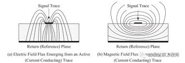

        On the one hand, crosstalk is one of the main sources of EMC. On the other hand, crosstalk interferes with the normal signal flow, which may cause data errors and is one of the main causes of bit errors.

        There is no certain pattern for the occurrence of problems. They appear and disappear from time to time. Diagnosis and location often take a lot of time and effort.

        Crosstalk is caused by electromagnetic coupling, which is divided into capacitive coupling and inductive coupling.

        Capacitive coupling is caused by the voltage change on the interference source (Aggressor) on the interfered object (Victim), which causes induced current and electromagnetic interference;

        Inductive coupling is caused by the magnetic field generated by the current change on the interference source, which causes induced voltage on the interfered object, causing electromagnetic interference. Therefore, when a signal passes through a conductor, it will cause two different types of noise signals on the adjacent conductor: capacitive coupling signal and inductive coupling signal.

        4.Power integrity
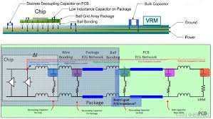

        Power integrity (PI) is abbreviated as PI, which is to confirm whether the voltage and current of the power source and the destination meet the requirements.

          Power integrity is very important in today’s electronic products. There are several levels of power integrity: chip level, chip packaging level, circuit board level and system level. The power integrity at the circuit board level must meet the following three requirements:

          (1) Make the voltage noise + voltage ripple of the chip pin smaller than the specification requirements (for example, the input voltage of the chip power pin requires the error between 1V to be less than +/-50 mV)

          (2) Control ground bounce (synchronous switching noise SSN, synchronous switching output SSO)

          (3) Reduce electromagnetic interference (EMI) and maintain electromagnetic compatibility (EMC): The power distribution network (PDN) is the largest conductor on the circuit board, and therefore it is also the antenna that is most likely to transmit and receive noise.

          Contact us for PCB quote now |

          5.Power supply noise

          When the signal state changes rapidly, ripple current will be generated in the power supply and ground. Due to the presence of inductance on the power supply and ground, the spike current generated by the signal mutation will cause voltage fluctuations on the power supply and ground.

          When dozens or even hundreds of signals in the system change state at the same time, it may cause system malfunction. Due to the complexity of power/ground noise, it is sometimes studied separately as power integrity.

            Sources of power supply noise:

            (1) The voltage output by the voltage regulator chip is not constant and has a certain amount of ripple.

            (2) The voltage regulator cannot respond to the rapid changes in the load’s current demand in real time. The frequency of the voltage regulator response is generally within 200Khz, and it can respond correctly. If it exceeds this frequency, a voltage drop will occur at the output short pin of the power supply.

            (3) The voltage drop caused by the load transient current in the power path impedance and the ground path impedance.

            (4) External interference.

            Five points should be paid attention to when calculating power supply noise:

            (1) What is the exact value of the output of the voltage regulator chip.

            (2) Is the working environment the environment recommended by the voltage regulator chip?

            (3) What is the load condition? This also affects the output of the voltage regulator chip.

            (4) Power supply noise will eventually affect the signal quality. The source of noise on the signal is not only the power supply noise, but also signal integrity problems such as reflection and crosstalk. Therefore, all noise margins cannot be left to the power supply system.

            (5) Different voltage levels have different requirements for power supply noise. The smaller the voltage, the smaller the noise margin. Analog circuits have higher power requirements.

            Post Tags: #pcb design#pcb Signal integrity

            Post navigation

            Previous Previous
            Buy rogers pcb material
            NextContinue
            EMC considerations for PCB design

            Search

            Search

            Products

            • HDI Multilayer PCB
            • Rigid Flex PCB
            • Flex pcb
            • High Frequency PCB
            • High speed pcb
            • Heavy copper PCB
            • Metal Core PCB
            • Ceramic PCB

            Address

            Andwin Circuits Co.,Limited
            Email: sales@andwinpcb.com
            Tel: +86 755 2832 9394
            Fax:+86 755 2992  6717
            ADD:1-2F-1217,HouDeQun Industrial park,
            NanTing RD NO.56,ShaJing,BaoAn,Shenzhen 518104,GuangDong,China

            Products

            • HDI Multilayer PCB
            • Rigid Flex PCB
            • Flex pcb
            • High Frequency PCB
            • High speed pcb
            • Heavy copper PCB
            • Metal Core PCB
            • Ceramic PCB

            Technology

            • Blogs
            • Via in pad
            • PCB E-test
            • PCB stack up
            • Metal core PCB panelization
            • Controlled impedance PCB

            CERTIFICATION

            Certification >>


            Copyright© 2003 - 2026 Andwin | All Rights Reserved | Powered by Andwin

            Scroll to top
            • Home
            • Products
              • HDI multilayer PCB
              • Rigid Flex PCB
              • Flex pcb
              • Special PCB
                • High Frequency PCB
                  • Rogers RO4350B PCB
                  • Rogers RO4003 pcb
                  • Rogers RO3003 PCB
                  • Rogers 5880 PCB
                  • DICLAD 527 PCB
                  • Taconic TLX series
                  • Taconic TLX-8 RF PCB
                  • Taconic TLX-9 RF PCB
                • High speed pcb
                  • Megtron 6 High Speed PCB
                  • TU-872 SLK Sp High Speed
                • High TG PCB
                  • SHENGYI SH260 PCB
                  • ISOLA 370HR PCB
                  • ISOLA IS410 PCB
                  • ISOLA IS420 PCB
                • Heavy copper PCB
                • Copper coin pcb
                • Copper inlay PCB
              • Metal Core PCB
                • Copper core pcb
                • Aluminum PCB
                • 2 Layers Aluminum PCB
                • Direct thermal MCPCB
                • 2 Layers Direct Thermal
              • Ceramic PCB
                • DPC ceramic PCB
                • DBC ceramic PCB
                • Thick film Ceramic PCB
                • Al2O3 Alumina PCB
                • AIN ALN ceramic PCB
                • IGBT Ceramic PCB
            • Service
              • PCB Assembly
              • Quick turn PCB assembly
              • PCBA conformal coating
            • Industry
              • Telecommunication
              • IoT and Wireless
              • Industrial Control
              • Thermal management
              • Power and Energy
              • IC test board
              • Automative
              • Medical
            • Capability
              • Rigid PCB
              • Rigid flex PCB
              • Metal core PCB
              • PCB Assembly
            • Technology
              • Blogs
              • Via in pad
              • PCB E-test
              • PCB stack up
              • MCPCB panelization
              • Controlled impedance PCB
            • About
              • About us
              • Certification
              • Factory Tour
            • Contact
            Search