The impact of crosstalk on signal transmission delay
In the previous articles “Why should DDR routing be on the same group and layer?”, we learned about the transmission speed of signals on transmission lines and the difference in delay between microstrip and stripline transmission. At the same time, many enthusiastic netizens also gave their own insights on the factors that affect transmission line delay, such as crosstalk, winding, vias, cross-splitting, etc. In this issue, we will continue to discuss the impact of crosstalk on signal delay under different modes through theoretical analysis and simulation verification.
Before starting the simulation, let’s briefly understand what crosstalk is and how it is formed. As shown in the figure below, when the spacing between the routing with signal transmission and the adjacent routing is close, the routing with signal transmission will cause noise on the adjacent routing. This phenomenon is called crosstalk.

The fundamental reason for the formation of crosstalk is the coupling between adjacent traces, as shown in the figure below:
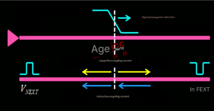
When a signal is transmitted on a trace, part of the energy will be coupled to the adjacent trace through electric field capacitive coupling and magnetic field inductive coupling, thereby causing crosstalk noise, and the crosstalk noise generated after coupling is divided into near-end crosstalk (VNEXT) and far-end crosstalk (VFEXT) according to the different directions of the crosstalk noise.
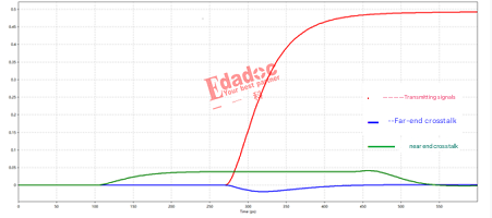
As shown in the figure below, taking the microstrip line as an example, when the transmission signal is a positive transition forward transmission, the near-end crosstalk will generate a positive transition pulse crosstalk noise, and the far-end crosstalk will generate a negative transition pulse crosstalk noise. The crosstalk of the inner layer trace is different from that of the microstrip line. The far-end crosstalk of the inner layer trace is almost 0. The detailed mechanism of crosstalk will not be introduced here. Interested friends can find relevant information for a deeper understanding.
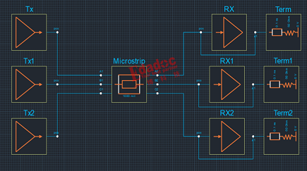
Next, we use the Sigrity Topology Explorer in Sigrity for simulation verification. In order to better reflect the impact of routing crosstalk on signal transmission delay under different modes, as shown in the figure below, three adjacent microstrip lines A, B, and C with a length of 1000 mil are simulated here for simulation.
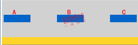
Among them, A and C are used as interference source signals, and B is used as the interfered signal. The simulation verification and comparison of the delay of the interfered signal B under the following three working conditions:
(1) no_crosstalk: There is no signal in A and C;
(2) even_crosstalk: A and C are in phase with B;
(3) odd_crosstalk: A and C are in phase with B;
The simulation link is built as shown in the figure below:
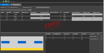
The stacking settings are shown in the figure below, where the line width is 5mil; the line spacing is 5mil.
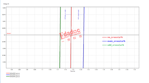
Simulation results:
The transmission delay of the signal in the even_crosstalk working state is about 10.9ps slower than that in the no_crosstalk working state;
The transmission delay of the signal in the odd_crosstalk working state is about 9.6ps faster than that in the no_crosstalk working state.
So what causes this difference in transmission delay?
I believe everyone has the answer in their mind, it is caused by crosstalk. Here we analyze the reasons for the difference based on the previous understanding of crosstalk. Taking the delay of the working state without crosstalk no_crosstalk as a reference, when the signal is in the even_crosstalk even-mode working state, the interference signal and the interfered signal jump in phase, so that the far-end crosstalk noise generated by the interference signal on the interfered signal is opposite to the jump direction of the interfered signal and is superimposed on the interfered signal, causing the edge jump of the interfered signal to arrive late.
When the signal is in the odd_crosstalk odd-mode working state, it is the opposite. The far-end crosstalk noise generated by the interference signal on the interfered signal is in the same direction as the jump direction of the interfered signal and is superimposed on the interfered signal, causing the edge jump of the interfered signal to arrive early.
From the above simulation verification, we know that crosstalk will affect the delay of the signal, so how can we avoid or reduce this effect?
Here, the editor took this opportunity to continue to perform simulation verification under the following conditions:
(1) Other conditions remain unchanged, the trace spacing is changed to 10mil, and the simulation results are shown in the figure below:
The transmission delay of the signal in the even_crosstalk even-mode working state is about 7.7ps slower than the transmission delay of the signal in the no_crosstalk working state without crosstalk;
The transmission delay of the signal in the odd_crosstalk odd-mode working state is about 7.6ps faster than the transmission delay of the signal in the no_crosstalk working state without crosstalk.

(2) Other conditions remain unchanged, the trace spacing is changed to 15mil, and the simulation results are shown in the figure below:
The transmission delay of the signal in the even_crosstalk even-mode working state is about 5.5ps slower than the transmission delay of the signal in the no_crosstalk working state without crosstalk;
The transmission delay of the signal in the odd_crosstalk odd-mode working state is about 5.4ps faster than the transmission delay of the signal in the no_crosstalk working state without crosstalk.
(3) With other conditions unchanged, the trace length is changed to 500mil, and the simulation results are shown in the figure below:
The transmission delay of the signal in the even_crosstalk working state is about 8.2ps slower than the transmission delay of the signal in the no_crosstalk working state without crosstalk;
The transmission delay of the signal in the odd_crosstalk working state is about 7.1ps faster than the transmission delay of the signal in the no_crosstalk working state without crosstalk.
From the above simulation results, it can be seen that for adjacent microstrip lines, increasing the trace spacing can weaken the coupling of the electric and magnetic fields between the traces, thereby reducing the far-end crosstalk noise generated on the interfered signal and reducing the delay difference between the traces caused by crosstalk; and reducing the coupling length of the trace can reduce the accumulation of far-end crosstalk noise, thereby reducing the delay difference between the traces caused by crosstalk.
In addition, for strip lines, far-end crosstalk is approximately 0, which means that far-end crosstalk has almost no effect on the signal delay of the inner layer. What needs to be paid attention to is the delay effect caused by near-end crosstalk between signals with opposite transmission directions. Therefore, routing in the inner layer can reduce the delay difference between the lines caused by far-end crosstalk.
Here comes the question
In the design of equal-length winding, such as the serpentine winding in DDR, how does it affect the delay of signal transmission?