Understanding and Mitigating Damage to Printed Circuit Boards (PCBs)
Introduction
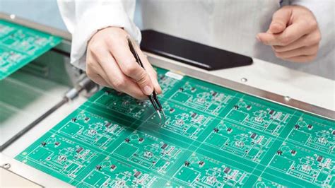
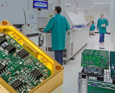
Printed Circuit Boards (PCBs) are the backbone of modern electronics, serving as the platform for interconnecting electronic components. They are used in a wide range of applications, from consumer electronics to industrial machinery, and even in aerospace and medical devices. However, despite their critical role, PCBs are susceptible to various forms of damage that can compromise their functionality and longevity. This article explores the common causes of PCB damage, the types of damage that can occur, and strategies for mitigating and repairing such damage.
Common Causes of PCB Damage
- Mechanical Stress:
- Physical Impact: Dropping or mishandling a PCB can lead to cracks, broken traces, or dislodged components.
- Flexing: Excessive bending or flexing of the PCB can cause stress fractures, especially in rigid-flex or flexible PCBs.
- Thermal Stress:
- Overheating: Excessive heat can cause solder joints to melt, components to fail, or the PCB substrate to delaminate.
- Thermal Cycling: Repeated heating and cooling can lead to thermal fatigue, causing cracks in solder joints or the PCB itself.
- Electrical Overload:
- Overvoltage: Applying a voltage higher than the PCB’s design specifications can cause traces to burn out or components to fail.
- Short Circuits: Accidental short circuits can lead to localized heating, burning out traces or components.
- Environmental Factors:
- Moisture: Exposure to high humidity or liquid spills can lead to corrosion, short circuits, or delamination.
- Contaminants: Dust, dirt, or chemical spills can cause electrical shorts or corrosion over time.
- UV Exposure: Prolonged exposure to ultraviolet light can degrade the PCB substrate and solder mask.
- Manufacturing Defects:
- Poor Soldering: Cold solder joints, solder bridges, or insufficient solder can lead to intermittent connections or short circuits.
- Incorrect Component Placement: Misaligned or incorrectly placed components can cause electrical issues or mechanical stress.
- Substandard Materials: Using low-quality materials can lead to premature failure under normal operating conditions.
Types of PCB Damage
- Trace Damage:
- Broken Traces: Physical impact or flexing can cause traces to break, disrupting electrical connections.
- Burned Traces: Overcurrent or short circuits can cause traces to overheat and burn out.
- Component Damage:
- Failed Components: Overheating, overvoltage, or manufacturing defects can cause components to fail.
- Dislodged Components: Mechanical stress or poor soldering can cause components to become dislodged from the PCB.
- Solder Joint Damage:
- Cracked Solder Joints: Thermal cycling or mechanical stress can cause solder joints to crack, leading to intermittent connections.
- Cold Solder Joints: Poor soldering techniques can result in weak or incomplete solder joints, leading to connection issues.
- Substrate Damage:
- Delamination: Excessive heat or moisture can cause the layers of the PCB to separate, leading to structural and electrical issues.
- Warping: Thermal stress can cause the PCB to warp, leading to mechanical and electrical problems.
- Corrosion:
- Metal Corrosion: Exposure to moisture or contaminants can cause the metal traces and components to corrode, leading to electrical failures.
- Solder Mask Degradation: UV exposure or chemical spills can degrade the solder mask, exposing the underlying traces to potential damage.
Mitigation Strategies
- Design Considerations:
- Robust Layout: Design the PCB with adequate trace widths, spacing, and thermal relief to minimize the risk of damage.
- Component Selection: Choose components with appropriate ratings for voltage, current, and temperature to avoid overloading.
- Environmental Protection: Incorporate protective coatings, conformal coatings, or enclosures to shield the PCB from moisture, dust, and UV exposure.
- Manufacturing Best Practices:
- Quality Control: Implement rigorous quality control measures to detect and correct manufacturing defects before the PCB is deployed.
- Proper Soldering: Ensure that soldering processes are optimized to produce strong, reliable solder joints.
- Material Selection: Use high-quality materials that can withstand the intended operating conditions.
- Operational Precautions:
- Temperature Management: Implement cooling solutions such as heatsinks, fans, or thermal vias to manage heat dissipation.
- Electrical Protection: Use fuses, circuit breakers, or surge protectors to prevent overvoltage or overcurrent conditions.
- Handling and Installation: Train personnel on proper handling and installation techniques to minimize mechanical stress.
- Regular Maintenance:
- Inspection: Periodically inspect the PCB for signs of damage, such as cracked solder joints, corroded traces, or dislodged components.
- Cleaning: Clean the PCB to remove dust, dirt, or contaminants that could lead to corrosion or short circuits.
- Testing: Perform functional testing to identify and address any electrical issues before they lead to failure.
Repair Techniques
- Trace Repair:
- Jumper Wires: Use thin wires to bridge broken traces and restore electrical connections.
- Conductive Ink: Apply conductive ink to repair minor trace damage or create new connections.
- Component Replacement:
- Desoldering: Use a desoldering tool to remove failed or damaged components.
- Resoldering: Solder new components in place, ensuring proper alignment and strong solder joints.
- Solder Joint Repair:
- Reflow Soldering: Use a reflow oven or hot air gun to reflow cracked or cold solder joints.
- Hand Soldering: Use a soldering iron to manually repair damaged solder joints.
- Substrate Repair:
- Epoxy Repair: Use epoxy resin to repair delaminated areas or reinforce weakened sections of the PCB.
- Mechanical Reinforcement: Add mechanical supports or braces to prevent further warping or flexing.
- Corrosion Mitigation:
- Cleaning: Use isopropyl alcohol or specialized cleaning solutions to remove corrosion from metal traces and components.
- Protective Coatings: Apply conformal coatings or protective sprays to prevent future corrosion.
Conclusion
PCBs are critical components in modern electronics, and their failure can have significant consequences. Understanding the common causes of PCB damage, the types of damage that can occur, and the strategies for mitigating and repairing such damage is essential for ensuring the reliability and longevity of electronic devices. By incorporating robust design practices, adhering to manufacturing best practices, taking operational precautions, and performing regular maintenance, the risk of PCB damage can be significantly reduced. Additionally, having the skills and tools to repair damaged PCBs can save time and resources, extending the life of electronic devices and reducing waste.
In conclusion, while PCBs are vulnerable to various forms of damage, proactive measures and effective repair techniques can help mitigate these risks and ensure the continued performance of electronic systems. As technology continues to advance, the importance of understanding and addressing PCB damage will only grow, making it a critical area of focus for engineers, technicians, and manufacturers alike.