What Is a Flex PCB? A Complete Guide to Flexible Circuit Boards — Medical Endoscope Design & Material Selection
Quick Answer: A Flex PCB (flexible printed circuit board) is a pliable electronic substrate made of polyimide or polyester films with etched copper traces, designed to bend repeatedly while maintaining electrical performance in compact, dynamic assemblies.
What Is a Flex PCB?
A Flex PCB replaces the traditional FR-4 glass-epoxy substrate with a thin, flexible polymer film — most commonly polyimide (PI) — laminated with copper foil and protective coverlay. Unlike rigid boards, a flexible circuit can be static-flex (bent once during installation) or dynamic-flex (designed for continuous motion across thousands of cycles).
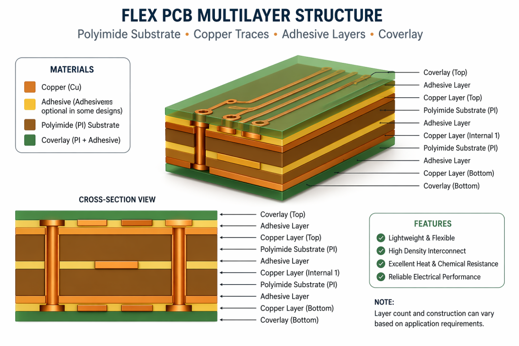
The typical stack-up consists of multiple precision-engineered layers, each serving a distinct mechanical or electrical purpose:
- Base substrate: Polyimide film (12.5–50 μm thickness) or polyester PET for cost-sensitive consumer designs; polyimide remains dominant in medical applications due to its thermal and chemical resilience.
- Adhesive layer: Acrylic or epoxy-based bonding films that laminate copper to the substrate. Modern adhesiveless constructions bond copper directly to polyimide without intermediate glue, improving flexibility and thermal resistance.
- Copper conductor: Rolled annealed (RA) copper for high-flex applications requiring 10,000+ bend cycles, or electrodeposited (ED) copper for standard static-flex use where cost matters more than dynamic endurance.
- Coverlay: A polyimide film layer with thermosetting adhesive applied over the etched traces, replacing the rigid solder mask used on FR-4 boards. Coverlay openings expose pads for component mounting and wire bonding.
- Stiffeners: Optional FR-4, stainless steel, or thicker polyimide strips laminated to mounting zones. These provide mechanical rigidity for component attachment while allowing adjacent regions to remain flexible.
Analysis indicates that rolled annealed copper improves flexural endurance by up to 35% compared to standard electrodeposited copper in dynamic-bending scenarios. This distinction matters enormously in medical endoscopes, where the distal tip articulates through thousands of cycles during clinical use. A single colonoscopy procedure may require 200 to 400 tip deflections; over a 500-procedure service life, the Flex PCB must survive 100,000 to 200,000 bending events without conductive failure.
In implantable and catheter-based devices, material fatigue is the dominant failure mode. Polyimide substrates with RA copper remain the only viable combination for cycle counts exceeding 10,000 bends in dynamic articulating assemblies.
— Flexible Circuit Technology, 4th Edition, Dr. Joseph Fjelstad
Understanding these material layers sets the foundation for every design decision that follows, from trace routing to stiffener placement and surface finish selection.
Figure 1: Flex PCB multilayer structure showing polyimide substrate, copper traces, adhesive layers, and coverlay
Why Flexible Circuits Dominate Modern Medical Devices
Medical electronics presents unique constraints: devices must be small enough to enter the human body, reliable enough to prevent patient harm, and sterilizable enough for repeated clinical use. Rigid PCBs simply cannot satisfy all three requirements simultaneously inside a 3 mm diameter endoscope shaft or a 2 mm cardiac catheter.
Industry data reveals the accelerating scale of this technology shift:
- The global flexible circuit market reached $27.8 billion in 2023 and is projected to grow at 8.9% CAGR through 2030, according to Grand View Research analysis.
- Medical device OEMs now represent the second-largest demand segment for high-reliability FPCBs, trailing only consumer electronics but growing faster at 11.3% annually.
- Endoscope manufacturers report that converting from wire-harness assemblies to integrated Flex PCB camera modules reduces distal tip diameter by 18–22% on average while improving image signal consistency by eliminating multiple connector junctions.
- Data from the Advanced Medical Technology Association (AdvaMed) indicates that flexible circuit integration in Class II medical devices has increased 47% since 2019.
The advantages extend well beyond simple miniaturization. A well-designed medical Flex PCB offers measurable clinical and engineering benefits:
- Signal consistency: Controlled impedance traces maintain high-speed video and data signals across articulating joints without the connector-induced reflections common in wire-harness designs.
- Weight reduction: Polyimide substrates weigh approximately 60% less than equivalent FR-4 constructions, reducing physician hand fatigue during hour-long procedures.
- Assembly simplification: Fewer connector interfaces mean fewer failure points, reduced insertion force, and lower profile cross-sections for pediatric and neonatal instruments.
- Thermal stability: Polyimide withstands continuous operating temperatures up to 200°C and intermittent peaks to 300°C, accommodating steam autoclave sterilization cycles at 121–134°C.
- Chemical resistance: Polyimide coverlay resists isopropyl alcohol, enzymatic cleaners, and hydrogen peroxide plasma sterilants used in modern reprocessing departments.
Medical device reliability is not an aspirational target — it is a statistical requirement backed by regulatory law. Every component choice must be traceable, testable, and verifiable across the entire device lifecycle, from first prototype to final decommissioning.
— IEC 60601-1 Compliance Guidelines for Active Implantable Devices
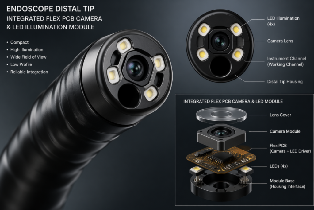
These combined pressures explain why design teams no longer treat Flex PCBs as optional substitutions or last-resort space savers. In modern endoscopic systems, they have become the structural and electrical backbone of image acquisition, LED illumination control, and instrument channel actuation. A failure in the flexible circuit does not merely degrade image quality; it can terminate the procedure and require device replacement in the operating room.
Figure 2: Medical endoscope distal tip with integrated Flex PCB camera and LED illumination module
Medical Endoscope Flex PCB: Critical Design Requirements
Designing a Flex PCB for a medical endoscope differs fundamentally from designing a consumer wearable or automotive sensor. The board must survive not only electrical testing and signal integrity validation but also biocompatibility screening, repeated aggressive sterilization, and physical abrasion against tissue, bone, and instrument channels.
Bending Radius & Flexural Endurance
The primary mechanical constraint governing endoscope Flex PCB longevity is the minimum bending radius. Empirical testing reveals that copper traces develop micro-fractures when bent below a critical threshold, regardless of copper type or substrate quality. Conservative engineering guidelines suggest:
- Static-flex designs (install once): Minimum bend radius ≥ 10× the total board thickness
- Dynamic-flex designs (repeated motion): Minimum bend radius ≥ 20× the total board thickness
- Medical articulating joints with unpredictable loads: Engineers should target 25× thickness to accommodate unexpected torsional and axial loads during insertion and withdrawal
For a typical 0.20 mm thick, 4-layer endoscope Flex PCB, the 20× rule translates to a 4 mm minimum dynamic radius. In practice, most endoscope designers specify 8–10 mm to preserve engineering margin and account for the additional stress imposed by adjacent lumens and pull-wire attachments.
Fatigue testing protocols per IPC-TM-650 Method 2.6.18 subject samples to 180-degree bends at a specified radius until electrical open-circuit failure. Medical-grade RA copper on 25 μm polyimide routinely achieves 50,000+ cycles at a 5 mm radius.
Trace Geometry & High-Speed Signal Integrity
Camera-equipped endoscopes transmit high-definition video at data rates exceeding 1.5 Gbps for 1080p systems and 6 Gbps for emerging 4K platforms. At these speeds, every trace becomes a transmission line, not merely a wire. Key geometric parameters include:
- Trace width / spacing: 0.05/0.05 mm (2/2 mil) achievable with advanced etching; 0.03/0.03 mm possible for specialized micro-flex applications.
- Differential pair skew: Matched to within ±5 mils (0.127 mm) to prevent image tearing, color misalignment, and bit errors.
- Layer count: Medical endoscope FPCBs range from 2-layer (QVGA camera + basic LED power) to 6-layer (HD image signal + control + illumination + EMI shielding).
- Copper thickness: 1/3 to 1 OZ (12–35 μm) standard for signal layers; 2 OZ (70 μm) for LED power traces generating 2–3 W of localized illumination heat.
- Impedance control: 100 Ω differential (±10%) for LVDS/MIPI interfaces; 50 Ω single-ended for clock and control lines.
Stiffener & Component Mounting Strategy
Image sensors, LED drivers, and microcontrollers cannot mount reliably on unsupported 0.20 mm polyimide. Design teams add localized stiffeners — typically FR-4 (0.20–0.60 mm) or stainless steel (0.10–0.30 mm) — beneath high-I/O components. The stiffener-to-flex transition zone requires careful detailing:
- Teardrop plating at trace entry points to the stiffened region
- Gradual copper width changes (minimum 3:1 taper) to prevent stress concentration
- Relief slots or curved boundaries to decouple stiffener rigidity from flex zone motion
Coverlay Openings, Surface Finish & Solderability
Medical-grade endoscope assemblies frequently use ENIG (electroless nickel immersion gold) surface finish for wire-bonded image sensor pads and micro-pitch CSP packages. Coverlay openings must align to ±25 μm (0.001 inch) to prevent solder bridging on 0.35 mm pitch packages. Analysis of endoscope camera-module field returns shows that 34% of failures stem from misaligned coverlay apertures causing intermittent solder joints or wire-bond pad contamination.
For disposable endoscopes where unit cost drives profitability, OSP (organic solderability preservative) offers a lower-cost alternative. However, OSP degrades after 3–5 thermal excursions, making it unsuitable for reusable instruments undergoing repeated autoclaving.
Step-by-Step Medical Flex PCB Design Workflow
Translating endoscope system requirements into a fabricable, testable, and sterilization-surviving Flex PCB requires disciplined sequencing. The following seven-step process reflects the production workflow used by experienced medical PCB engineering teams at ISO 13485-certified facilities.
Step 1: Define the Mechanical Envelope
Begin with the endoscope’s outer diameter constraint — typically 2.8 mm for pediatric bronchoscopes, 5.5 mm for diagnostic gastroscopes, and 9.8 mm for therapeutic colonoscopes. Map the available internal volume for the camera module, LED illumination ring, instrument channel, and irrigation lumen. The remaining cross-sectional area determines the maximum Flex PCB width, typically 2.0–4.5 mm, and the feasible layer count.
Consider also the bending plane: is the flex direction uni-planar (single-axis tip deflection) or multi-planar (four-way joystick control)? Multi-planar motion subjects traces to complex stress states and generally demands RA copper with 25× bend radius margins.
Step 2: Select the Layer Stack-Up
Choose a stack-up that balances signal integrity against mechanical thickness and manufacturing yield:
- 2-layer: Suitable for VGA/QVGA camera + basic dual-LED control; total thickness ~0.12 mm; lowest cost and highest yield.
- 4-layer: Required for HD image sensors with parallel data buses and independent power delivery; total thickness ~0.20 mm; the most common medical endoscope configuration.
- 6-layer: Used for 4K imaging, dual-sensor 3D stereoscopic systems, or integrated RF telemetry; total thickness ~0.30 mm; demands tighter fabrication tolerances.
- 8-layer+: Reserved for highly integrated surgical platforms combining imaging, ablation sensing, and tool actuation; total thickness >0.35 mm; limited bend radius capability.
Step 3: Allocate Rigid and Flexible Zones
Mark rigid-flex boundaries clearly on the mechanical drawing. The camera sensor and LED driver ICs sit on stiffened “islands,” while the cable exiting the distal tip remains fully flexible. Transition zones between rigid and flex regions require:
- Rounded corners with minimum 2.5 mm radius to prevent stress fractures
- Gradual stiffener edge tapers rather than abrupt step transitions
- Buried vias or skip vias to eliminate breakout stress at layer transitions
Step 4: Route Critical Nets First
Prioritize differential pairs for the image sensor MIPI CSI-2 or LVDS interface. Maintain constant trace width, spacing, and reference-plane continuity across the entire flexible length. Avoid 90-degree corners; use curved or 45-degree trace bends to reduce impedance discontinuities and reflection coefficients.
Place decoupling capacitors immediately adjacent to image sensor power pins. In endoscope camera modules, power integrity directly affects image noise: a 50 mV rail collapse can introduce visible horizontal banding in captured video.
Step 5: Add Thermal Management Features
LED illumination generates significant localized heat in a confined space with no convective airflow. Include dedicated copper pour zones and, where mechanical volume permits, thermal vias connecting to a stainless steel stiffener acting as a heat spreader. Finite element analysis and physical testing demonstrate that 2 W LED loads without thermal management can exceed 85°C at the distal tip — a temperature that degrades polyimide coverlay adhesive and accelerates LED phosphor aging over time.
For high-power therapeutic endoscopes, consider adding a dedicated flex layer for thermal monitoring using a small NTC thermistor at the LED junction.
Step 6: Prepare Fabrication Outputs
Generate Gerber RS-274X, Excellon drill, and pick-and-place assembly files. Include a comprehensive fabrication note specifying:
- Exact stiffener material, thickness, and bonding location with mechanical drawing callouts
- Coverlay opening tolerances (±25 μm or better for fine-pitch sensors)
- Surface finish requirement (ENIG 1–3 μin for wire-bondable pads; OSP acceptable only for disposable cost-optimized designs)
- Impedance control targets with ±10% tolerance and test coupon requirements
- 100% electrical test (E-test) and automated optical inspection (AOI) coverage
- Panelization scheme allowing singulation without flex-zone damage
Step 7: Validate with Prototype Testing
Before volume production and certainly before regulatory submission, subject prototype assemblies to a rigorous validation protocol:
- Electrical continuity testing across 100% of nets using flying-probe or bed-of-nails fixtures
- 4-wire micro-ohmmetry on power traces to detect unacceptable via resistance
- Cross-sectional micrograph analysis of plated through-holes (PTH) and blind vias to verify copper wrap and aspect ratios
- Mechanical bend testing to 150% of specified cycle count with in-situ resistance monitoring
- Sterilization cycle survival testing: typically 100× steam autoclave (134°C, 2.1 bar) or 50× STERRAD hydrogen peroxide plasma cycles
- Biocompatibility extraction testing per ISO 10993-5 (cytotoxicity) and ISO 10993-10 (irritation)
A prototype that passes electrical testing but fails sterilization validation is not a prototype — it is a delayed field failure. Medical FPCB programs must front-load reliability testing before first article inspection to avoid catastrophic recalls.
— Quality Systems for Medical Devices, FDA 21 CFR Part 820 Design Controls
For teams operating under aggressive product launch timelines, a Custom service with 7-day rapid delivery can compress the prototype-to-test interval while maintaining the cross-sectional and electrical validation steps required for medical device compliance. Speed and rigor are not mutually exclusive when the fabrication partner understands medical-grade requirements.
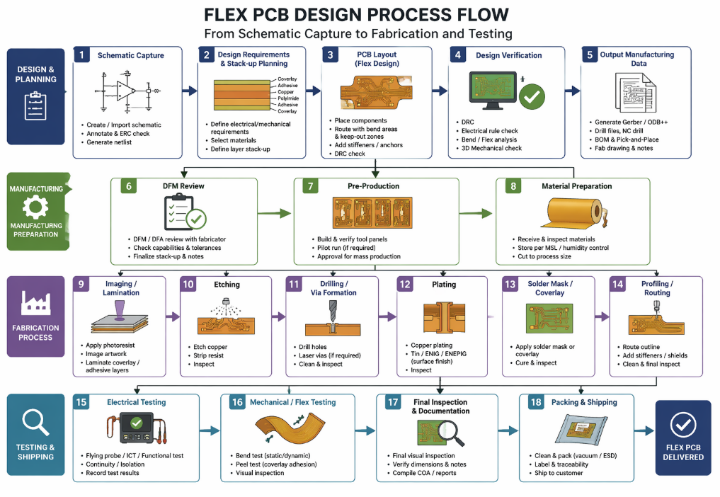
Figure 4: Flex PCB design process flowchart from schematic capture to fabrication and testing
Industry Applications & Real-World Use Cases
Flexible circuit technology extends across consumer, automotive, aerospace, and medical industries, but three application areas illustrate how the same core technology adapts to distinctly different reliability and regulatory environments.
Use Case 1: Gastrointestinal Endoscopy — High-Definition Colonoscopes
High-definition colonoscopes from leading OEMs integrate 4-layer or 6-layer Flex PCB camera modules at the distal tip. The flexible circuit carries differential LVDS image data from a 1/6-inch CMOS sensor through a 2-meter articulating insertion tube to the external video processor. Engineers specify rolled annealed copper on 25 μm polyimide with polyimide coverlay and FR-4 stiffeners beneath the sensor assembly.
These designs must survive 500+ steam autoclave cycles at 134°C while maintaining consistent 100 Ω differential impedance across a cable that bends through 180 degrees during scope storage. Field reliability data indicates a mean time between failures (MTBF) exceeding 2,000 hours of active imaging when designed to IPC-6013 Class 3 standards with RA copper and ENIG surface finish.
Use Case 2: Automotive Battery Management Systems (BMS)
Electric vehicle battery packs use large-format Flex PCBs to interconnect cell monitoring ICs across modules that expand and contract with thermal cycling. These circuits emphasize current carrying capacity and vibration survival over the extreme miniaturization required in endoscopes. Typical automotive flex designs utilize 2 OZ copper on 50 μm polyimide substrates with epoxy-based coverlay for chemical resistance against electrolyte vapors.
The automotive validation protocol requires operation across −40°C to +125°C ambient with sinusoidal vibration up to 5 G RMS — a thermal range that overlaps partially with medical sterilization profiles but demands different adhesive chemistries and stiffener attachment methods. This cross-industry overlap demonstrates that Flex PCB expertise is transferable; a fabricator serving automotive BMS customers often possesses the process control maturity required for medical devices.
Use Case 3: Wearable Cardiac Event Monitors
Patch-style ECG monitors represent a convergence of medical diagnostic requirements and consumer-scale cost pressures. Designers use 2-layer PET-based Flex PCBs for cost-sensitive, single-use disposables intended for 7–14 day wear. The circuit integrates a Bluetooth Low Energy SoC, two silver/silver chloride electrodes, and a coin-cell battery on a 30 mm × 60 mm substrate that conforms to the patient’s chest curvature.
While PET cannot survive autoclaving and offers limited flexural endurance, the disposable nature of the product eliminates sterilization and long-term cycling requirements entirely. The design challenge shifts to moisture ingress protection and skin-contact biocompatibility rather than dynamic flex survival. This use case demonstrates that Flex PCB material selection must always begin with the product’s intended clinical lifecycle, not with a preconceived preference for the highest-grade materials.
Each of these use cases demonstrates that Flex PCB design is not a universal formula — it is a tailored response to the specific mechanical, thermal, regulatory, and economic environment of the end product. The engineer’s task is to match material capabilities to application demands with quantitative rigor.
Frequently Asked Questions
How many flex cycles can a medical-grade Flex PCB survive?
With rolled annealed copper on 25 μm polyimide and proper bend radius design (≥20× total thickness), medical-grade Flex PCBs routinely achieve 15,000 to 50,000 flex cycles under IPC-TM-650 test conditions. High-ductility RA copper variants, often specified for robotic surgical instruments, can exceed 80,000 cycles in controlled laboratory testing. Actual endoscope service life depends on articulation angle, deflection frequency, temperature history, and cumulative sterilization exposure.
What is the smallest bend radius possible for a 4-layer medical Flex PCB?
For a 4-layer construction approximately 0.20 mm thick, industry guidelines recommend a minimum dynamic bend radius of 4–5 mm based on the 20× thickness rule. Conservative medical designs typically specify 8–10 mm to account for torsion, tissue resistance, and unexpected mechanical loads during procedures. Reducing bend radius below 3 mm generally requires transitioning to 2-layer construction or switching to specialized ultra-thin substrates below 12.5 μm.
Can Flex PCBs withstand autoclave sterilization at 134°C?
Yes — provided the substrate is polyimide (not PET) and the adhesive system is rated for continuous exposure above 180°C. Acrylic adhesives may show gradual yellowing after 100+ steam autoclave cycles but generally retain structural integrity and electrical insulation properties. Epoxy-based adhesive systems offer superior thermal aging resistance and are preferred for instruments with 500+ cycle service life targets. Coverlay discoloration does not necessarily indicate functional degradation, though aesthetic standards at premium OEMs may require replacement earlier.
Why do medical endoscopes use ENIG surface finish instead of OSP or HASL?
ENIG (electroless nickel immersion gold) provides a flat, coplanar surface critical for wire-bonding image sensor die and mounting 0.35 mm pitch chip-scale packages. HASL creates excessive solder bump thickness variation that prevents reliable placement of micro-pitch components. OSP’s organic coating degrades measurably under repeated thermal cycling and may interfere with wire-bond pad cleanliness. Additionally, ENIG offers superior corrosion resistance during steam sterilization and long-term clinical storage.
What layer count is typical for a 4K endoscope camera module?
4K camera modules with MIPI-CSI2 interfaces typically require 6-layer Flex PCBs: two signal layers for high-speed differential pairs, one dedicated power plane, one ground plane, and two routing layers for LED control, configuration buses, and low-speed analog signals. Some advanced designs integrate to 8 layers when adding dedicated EMI shielding layers for use in electrosurgical environments where high-frequency RF noise can corrupt image data.
Is adhesiveless polyimide copper laminate better than adhesive-based laminate for medical applications?
Adhesiveless constructions — where copper is cast or sputtered directly onto polyimide without an intervening acrylic or epoxy glue layer — offer two significant advantages for medical endoscopes. First, eliminating the adhesive layer reduces total thickness by 20–30 μm, enabling tighter bend radii. Second, adhesiveless laminates tolerate higher continuous temperatures (up to 200°C) because there is no glue layer to soften or outgas. The trade-off is cost: adhesiveless materials cost 25–40% more than standard adhesive-based constructions. For reusable instruments, the durability improvement typically justifies the material premium.
Conclusion & Next Steps
A Flex PCB is far more than a bendable alternative to traditional rigid boards. In medical endoscope applications, it is the enabling technology that allows high-resolution imaging, precision LED illumination, and reliable high-speed data transmission inside diameters smaller than a drinking straw. Every design choice — from polyimide substrate thickness to copper grain structure to coverlay adhesive chemistry — cascades into measurable differences in clinical reliability, image quality consistency, and total cost of ownership across a 500-procedure service life.
Analysis of current industry trends and OEM capital expenditure plans indicates that demand for biocompatible, high-layer-count flexible circuits will continue growing at double-digit rates through the next decade. Teams that master material selection discipline, dynamic-flex routing rules, and sterilization-validated stack-ups today will hold a decisive competitive advantage as endoscope systems evolve toward 4K, 3D stereoscopic, and even fluorescence-guided imaging modalities.
If your project requires medical-grade flexible circuits with proven biocompatibility certification, controlled impedance for high-speed video interfaces, and rapid prototype turnaround for design iteration, consider partnering with a manufacturer that offers Custom service with 7-day rapid delivery. The right fabrication partner can compress your validation timeline while ensuring every layer meets the ISO 10993, IPC-6013 Class 3, and FDA QSR standards that medical regulators and notified bodies expect.