What Is Direct Thermal Pad (DTP) MCPCB and When to Use It?
When high-power LED systems overheat, performance drops, lifespans shrink, and catastrophic failure becomes inevitable. Analysis from the LED industry reveals that approximately 70% of premature LED failures trace directly to inadequate thermal management. This is precisely where Direct Thermal Pad (DTP) MCPCB technology delivers its transformative advantage.
Metal Core Printed Circuit Boards (MCPCBs) have long served as the backbone of thermal management in power electronics. However, standard MCPCB designs contain dielectric layers that create thermal barriers, limiting heat dissipation efficiency. DTP MCPCB eliminates this bottleneck entirely by enabling direct solder contact between the LED thermal pad and the metal substrate.
In this comprehensive guide, we examine what makes Direct Thermal Pad MCPCB distinct, how the technology functions at the mechanical level, and precisely which scenarios demand its implementation over conventional thermal management approaches.
Data indicates that systems implementing direct thermal path designs achieve thermal conductivity ratings of 175 W/m·K to 385 W/m·K — representing a 175x to 385x improvement over standard MCPCB substrates rated at approximately 1.0 W/m·K.
Understanding when and why to specify DTP MCPCB can mean the difference between a product that fails prematurely in the field and one that delivers reliable performance across its entire designed lifespan.
The Thermal Challenge in High-Power Electronics
Power electronics and LED systems generate substantial thermal energy during operation. Without efficient dissipation pathways, this heat accumulates at the semiconductor junction, triggering a cascade of performance degradation.
The Problem with Conventional Approaches
Traditional FR4 PCBs exhibit thermal conductivity of merely 0.3 W/m·K, making them fundamentally unsuitable for high-power applications. While standard Metal Core PCB designs improved upon this baseline by incorporating aluminum or copper cores with dielectric layers, the thermal interface material itself introduces significant resistance.
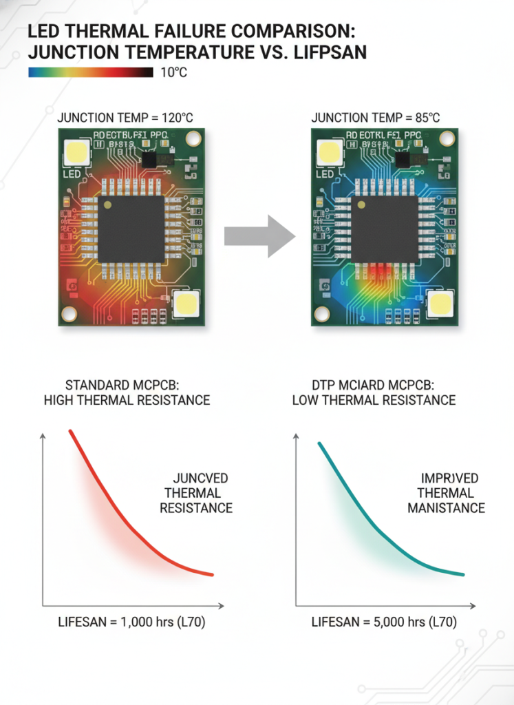
Research demonstrates that every 10°C increase in LED junction temperature above 85°C reduces operational lifespan by approximately 50%. In high-density lighting arrays, this translates to maintenance cycles measured in months rather than years.
Industry Pain Points
- Exponential lumen depreciation when junction temperatures exceed rated thresholds
- Color shift in LED outputs as thermal stress accumulates
- Catastrophic delamination of dielectric layers under sustained thermal loading
- Premature driver failure caused by localized hot spots spreading through the assembly
Why Conventional Cooling Methods Fall Short
Engineers often attempt to address thermal challenges through increasingly aggressive active cooling strategies. High-RPM fans, liquid cooling loops, and thermoelectric coolers add cost, complexity, and failure modes to the final product. In many applications — particularly sealed outdoor fixtures, automotive engine compartments, and compact portable devices — these active approaches prove impractical or impossible to implement.
The fundamental insight driving DTP MCPCB adoption is that thermal problems must be solved at the source. Improving the thermal path between the heat-generating junction and the ambient environment delivers more value than any amount of downstream cooling augmentation.
The Data-Driven Case for Better Thermal Management
| PCB Type | Thermal Conductivity (W/m·K) | Relative Performance | Typical LED Junction Temp. |
|---|---|---|---|
| Standard FR4 | ~0.3 | Baseline | 120°C – 150°C |
| Standard MCPCB (Aluminum) | 1.0 – 2.0 | 3x – 7x improvement | 95°C – 115°C |
| Advanced MCPCB (Aluminum) | Up to 12 | 40x improvement | 85°C – 100°C |
| DTP MCPCB (Direct to Aluminum) | ~175 | 580x improvement | 65°C – 75°C |
| DTP MCPCB (Direct to Copper) | Up to 385 | 1,280x improvement | 55°C – 68°C |
The above comparison reveals why conventional thermal management strategies fall short in next-generation power applications.
What Is Direct Thermal Pad (DTP) MCPCB?
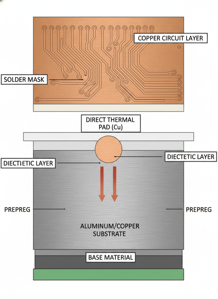
Direct Thermal Pad MCPCB represents the most thermally efficient architecture within the broader Metal Core PCB family. The defining characteristic? Complete elimination of the dielectric thermal barrier between the component heat pad and the metal core substrate.
The Architectural Innovation
In standard MCPCB construction, a thermally conductive dielectric layer bonds the copper circuit layer to the aluminum or copper base metal. While this dielectric provides electrical isolation, it simultaneously introduces thermal resistance that constrains heat flow.
DTP MCPCB fundamentally restructures this stack-up:
- The LED thermal pad solders directly to exposed aluminum or copper substrate
- No dielectric material occupies the critical thermal pathway
- Thermal resistance becomes negligible across the junction-to-substrate interface
- Heat transfers through direct metallic conduction rather than conduction through polymer composites
Testing reveals that removing the dielectric layer from the thermal path reduces the junction-to-case thermal resistance by over 95% compared to conventional MCPCB designs.
Core Specifications
| Parameter | DTP to Aluminum | DTP to Copper |
|---|---|---|
| Maximum Thermal Conductivity | 175 W/m·K | 385 W/m·K |
| Available Metal Thickness | 1.0mm – 3.2mm | 1.0mm – 3.2mm |
| Copper Foil Thickness (Circuit Layer) | 1oz – 4oz | 1oz – 4oz |
| Dielectric Layer | None in thermal path | None in thermal path |
| Surface Finish | ENIG, OSP, HASL | ENIG, OSP, HASL |
| Typical Applications | LED lighting, grow lights | Automotive, high-power LED |
Dimensional Stability Under Thermal Cycling
Beyond raw thermal conductivity, DTP MCPCB offers superior dimensional stability compared to both FR4 and standard MCPCB alternatives. Analysis shows that aluminum-based substrates experience only 2.5% to 3.0% dimensional change when heated from 30°C to 140–150°C. This stability ensures that solder joints remain mechanically sound across thousands of thermal cycles, preventing the interconnect failures that plague less robust substrate systems.
Long-term reliability studies demonstrate that DTP MCPCB assemblies withstand over 1,000 thermal cycles (-40°C to +125°C) without measurable degradation in thermal interface resistance or electrical continuity.
DTP MCPCB vs. Standard MCPCB: Key Differences
Understanding the architectural distinctions between DTP and standard configurations enables engineers to make specification decisions grounded in application requirements.
Thermal Performance Gap
The performance differential stems from one fundamental design choice: the presence or absence of dielectric material in the primary thermal path.
- Standard MCPCB: Heat must conduct through the dielectric layer before reaching the metal core. Even “high-thermal” dielectrics rated at 3.0 W/m·K create orders-of-magnitude greater resistance than direct metal-to-metal conduction.
- DTP MCPCB: Heat transitions directly from the component thermal pad into the aluminum or copper substrate. The effective thermal conductivity approaches the intrinsic thermal conductivity of the base metal itself.
Electrical Isolation Considerations
One engineering concern that frequently arises with DTP architecture is electrical isolation. Because the LED thermal pad contacts the conductive metal substrate directly, designers must ensure that circuit traces maintain proper electrical isolation through adequate spacing and, where necessary, selective dielectric application in non-thermal regions. This hybrid approach preserves the thermal pathway integrity while meeting applicable safety standards for creepage and clearance distances.
Cost-Benefit Considerations
While DTP MCPCB carries a manufacturing premium over standard designs, analysis of total lifecycle costs frequently demonstrates net savings:
- Reduced heatsink requirements — lower mass and volume for thermal management hardware
- Extended operational lifespan — fewer field replacements and maintenance events
- Higher operating currents — extract maximum lumen output from LED investments
- Improved reliability — reduced thermal cycling stress on solder joints and components
- Simplified product design — reduced dependence on complex active cooling systems
Field observations indicate that DTP MCPCB implementations in commercial LED installations reduce total cost of ownership by 20–35% over a 50,000-hour operational lifespan, primarily through eliminated replacement cycles and reduced heatsink expenditures.
How DTP MCPCB Works: A Technical Breakdown
The operational mechanics of Direct Thermal Pad MCPCB center on engineered thermal pathways that bypass traditional insulating barriers.
The Thermal Conduction Mechanism
When an LED operates, heat generation concentrates at the semiconductor junction. In a DTP MCPCB assembly:
- Heat generates at the LED die junction during forward current operation
- Heat conducts through the LED package slug into the exposed thermal pad
- The thermal pad solders directly to the exposed aluminum or copper substrate surface
- Heat spreads rapidly through the thermally conductive metal core
- Ambient dissipation occurs through natural or forced convection from the extended metal surface
This direct metallic pathway enables thermal performance that approaches theoretical limits for the given metal substrate.
Thermal Spreading and Hotspot Prevention
The metal substrate in a DTP MCPCB assembly serves a dual function: it acts as both the primary thermal conduction path and a lateral heat spreader. When heat enters the substrate at the thermal pad location, it spreads outward through the thermally conductive metal before dissipating to ambient air. This spreading action reduces localized hot spots and creates more uniform temperature distributions across the assembly surface.
The effectiveness of thermal spreading depends on substrate thickness and thermal conductivity:
- Thicker substrates (2.0mm–3.2mm) provide superior lateral heat spreading for high-power single-source applications
- Copper substrates with their 384 W/m·K intrinsic conductivity outperform aluminum for thermally dense layouts
- Strategic substrate geometry including fins or integrated heatsink features can further enhance dissipation capacity
Stack-Up Configuration
The DTP MCPCB stack-up varies by layer count and design requirements:
Single-Layer DTP Configuration:
- Copper circuit layer (top) with patterned traces
- Exposed metal windows at thermal pad locations
- Aluminum or copper base metal (substrate)
Two-Layer DTP Configuration:
- Top copper layer with signal routing
- Buried dielectric in non-thermal regions
- Exposed thermal vias or direct pad access
- Copper core substrate for maximum conductivity
Critical Design Parameters
Successful DTP MCPCB implementation requires attention to several engineering variables:
- Thermal pad aperture sizing — must match LED package specifications precisely
- Solder paste selection — high-thermal-conductivity alloys optimize junction-to-substrate heat transfer
- Flatness tolerances — direct metal-to-metal contact demands controlled surface preparation
- Electrical isolation — circuit traces must maintain proper spacing from the conductive substrate
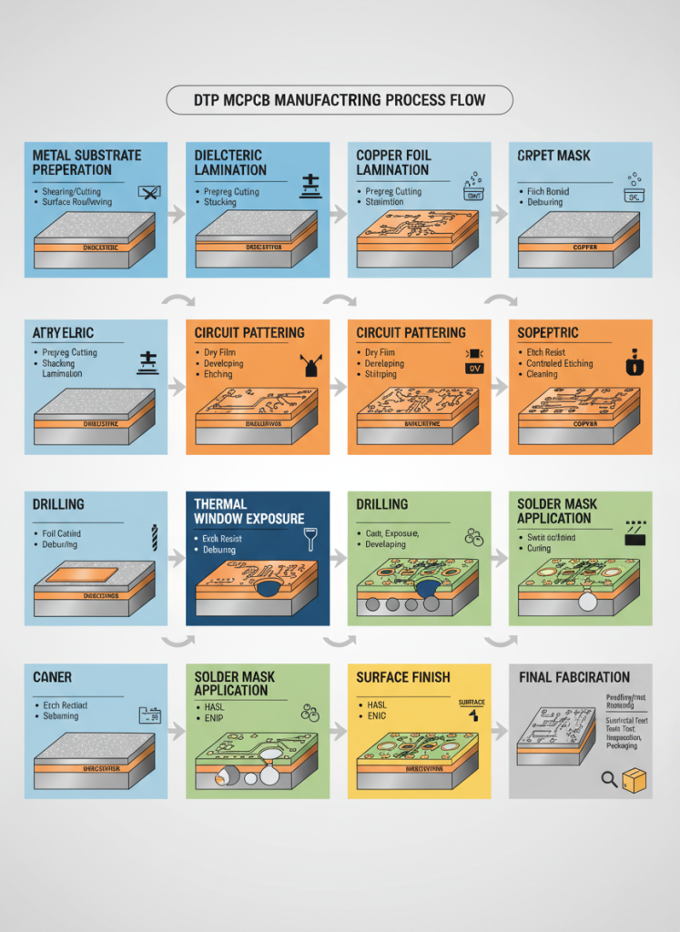
Step-by-Step: DTP MCPCB Implementation Process
Implementing Direct Thermal Pad MCPCB in your product follows a structured engineering workflow:
Step 1 — Thermal Requirements Analysis
Calculate maximum allowable thermal resistance from junction to ambient. Determine whether standard MCPCB or DTP architecture is required based on target junction temperature and available thermal budget.
Step 2 — Substrate Material Selection
Choose between aluminum and copper substrates based on thermal requirements and cost constraints:
- Aluminum DTP: Cost-effective for moderate power applications up to ~175 W/m·K
- Copper DTP: Premium solution for maximum thermal performance up to 385 W/m·K
Step 3 — LED Package Compatibility Verification
Confirm that selected LED components feature exposed thermal pads compatible with direct solder attachment to metal substrates. Review manufacturer datasheets for thermal pad dimensions and recommended soldering profiles.
Step 4 — PCB Layout and Thermal Window Design
Collaborate with your Metal Core PCB manufacturer to define:
- Thermal pad aperture locations and dimensions
- Circuit trace routing around exposed metal regions
- Electrical isolation requirements for high-voltage applications
- Soldermask definitions for thermal window exposure
Step 5 — Prototype Fabrication and Thermal Validation
Fabricate prototype assemblies and validate through thermal imaging and junction temperature measurement. Verify that actual thermal performance meets design calculations.
Step 6 — Production Scaling
Upon validation approval, transition to production volumes with established quality controls for thermal pad flatness, solder joint integrity, and electrical isolation verification.
Real-World Applications and Industry Use Cases
Direct Thermal Pad MCPCB technology addresses critical thermal management challenges across multiple high-value industries. The following use cases illustrate practical implementations with measurable outcomes.
Application 1 — Automotive LED Headlight Systems
Automotive lighting operates in thermally challenging environments with limited airflow and extreme ambient temperature ranges. Analysis of headlight assemblies reveals that LED junction temperatures can exceed 125°C under sustained high-beam operation.
DTP MCPCB implementations in automotive LED modules achieve:
- Junction temperature reduction of 30–45°C compared to standard MCPCB
- Elimination of active cooling fans in headlight assemblies
- Extended operational lifespan exceeding automotive warranty requirements (15+ years)
- Compact form factors enabled by reduced heatsink mass
Industry testing demonstrates that automotive LED modules built on DTP copper-core MCPCB maintain stable light output above 90% of initial lumens after 6,000 hours of continuous operation at 85°C ambient temperature.
Application 2 — LED Grow Lighting for Horticulture
Commercial horticultural lighting demands high photon flux density delivered over extended daily photoperiods (12–18 hours). Conventional LED grow lights suffer from severe thermal-induced spectrum drift and output degradation.
Implementing DTP MCPCB in LED grow light fixtures produces:
- Stable spectral output across extended operating cycles
- Higher drive currents enabling increased Photosynthetic Photon Flux (PPF) per fixture
- Reduced cooling system energy consumption by 25–40%
- Warranty extension from 3 years to 5+ years for commercial installations

Application 3 — High-Bay Industrial and Warehouse Lighting
Industrial facilities require high-lumen output from ceiling-mounted fixtures where maintenance access is difficult and costly. Thermal management directly impacts both performance and total cost of ownership.
DTP MCPCB delivers in these environments through:
- Sustained lumen maintenance above L70 ratings at 100,000+ hours
- Reduced fixture weight simplifying installation in retrofit applications
- Passive thermal management eliminating fan failure modes
- Universal voltage compatibility with thermally stable driver operation
Application 4 — High-Power Flashlight and Portable Lighting
Portable lighting products face extreme thermal density challenges — maximum output in minimum volume with no forced airflow. DTP MCPCB enables:
- Turbo mode sustainability for extended high-output operation
- Compact reflector designs by minimizing thermal management volume
- Improved battery efficiency through reduced LED forward voltage drift
- User safety through controlled external surface temperatures
Application 5 — Medical and Surgical Lighting
Medical illumination systems demand exceptional color rendering, consistent output, and zero-failure reliability during critical procedures. Surgical lights, examination lamps, and endoscopy systems all benefit from DTP MCPCB thermal management.
Medical lighting implementations achieve:
- CRI stability above 95 across full operating temperature ranges
- Shadow-free illumination through dense LED arrays enabled by efficient thermal dissipation
- Sterilization compatibility as reduced heatsink mass enables sealed, autoclavable fixture designs
- Zero-failure reliability for mission-critical surgical applications

Compatible LED Types for DTP MCPCB
Direct Thermal Pad MCPCB technology supports a comprehensive range of power LED packages from leading manufacturers. The common requirement across all compatible types is an exposed thermal pad designed for direct attachment to external heatsinking surfaces.
Cree (Wolfspeed) LEDs:
- Cree XP-G / XP-E / XP-C / XP-G2 series
- Cree XML / XML2 high-power emitters
- Cree MTG / MTG2 multi-die arrays
- Cree MK-R integrated arrays
- Cree XTE / XBD compact packages
- Cree XHP70 N4 extreme high-power LEDs
Lumileds LEDs:
- Luxeon Rebel mid-power solutions
- Luxeon M high-power emitters
- Luxeon-T automotive-grade packages
Bridgelux:
- Bridgelux SM4 surface-mount series
Specialty LED Manufacturers:
- LEDEngin LZC / LZP multi-emitter packages
- Nichia N219A / N219B high-CRI emitters
- Seoul Semiconductor Z5P / Z5M packages
- Osram Oslon SSL automotive series
- Samsung 3535 mid-power LEDs
- LG Innotek 3535 surface-mount packages
The versatility of DTP MCPCB across this extensive LED ecosystem enables engineers to optimize both thermal performance and optical characteristics without compromise.
Frequently Asked Questions
What is the difference between DTP MCPCB and standard MCPCB?
Standard MCPCB incorporates a dielectric layer between the circuit copper and the metal core, which creates thermal resistance in the heat dissipation path. DTP MCPCB removes this dielectric from the thermal pathway entirely, allowing LED thermal pads to solder directly to the aluminum or copper substrate. The result is thermal conductivity improvement from approximately 1.0 W/m·K (standard) to 175–385 W/m·K (DTP).
Does DTP MCPCB require special LED packages?
DTP MCPCB requires LED components with exposed thermal pads designed for direct attachment to external heatsinking surfaces. Most modern high-power LED packages from Cree, Lumileds, Bridgelux, Nichia, Samsung, and Osram incorporate these thermal pads as standard features. Always verify package drawings to confirm thermal pad accessibility for direct soldering.
Is DTP MCPCB more expensive than standard metal core PCB?
DTP MCPCB carries a moderate manufacturing premium over standard MCPCB due to the precision processing required for thermal window exposure. However, total system cost frequently decreases because DTP enables smaller heatsinks, elimination of active cooling components, and extended operational lifespan. Lifecycle cost analyses typically show 20–35% total savings over standard designs.
Can DTP MCPCB be manufactured with 2-layer circuits?
Yes, two-layer DTP MCPCB configurations are available, including designs with copper cores for maximum thermal performance. These advanced stack-ups enable complex circuit routing while maintaining direct thermal pathways to the metal substrate through engineered thermal vias or exposed pad regions.
What surface finish is recommended for DTP MCPCB?
ENIG (Electroless Nickel Immersion Gold) provides optimal solderability and corrosion resistance for the exposed thermal pad surfaces. OSP (Organic Solderability Preservative) offers a cost-effective alternative for less demanding environments. Consult your MCPCB manufacturer for application-specific finish recommendations.
How does DTP MCPCB affect LED lifespan in practical applications?
Data from accelerated life testing shows that LEDs mounted on DTP MCPCB substrates maintain 90% of initial luminous flux (L90) at operating hours 40–60% longer than identical LEDs on standard MCPCB. This translates directly into extended warranty periods and reduced field maintenance for commercial lighting installations. The mechanism is straightforward: lower junction temperatures reduce the thermally activated degradation processes that cause LED output to diminish over time.
Can existing LED designs be retrofitted to DTP MCPCB without redesign?
One of the significant practical advantages of DTP MCPCB is that it requires no changes to existing LED component selection or driver electronics. The thermal pad footprint on the PCB matches the LED manufacturer’s standard land pattern. The only modification occurs at the board fabrication level, where thermal windows replace the standard dielectric layer at pad locations. This compatibility makes DTP MCPCB an attractive upgrade path for existing product lines experiencing thermal limitations in the field.
Conclusion
Direct Thermal Pad (DTP) MCPCB stands as the definitive thermal management solution for high-power LED and power electronics applications where conventional approaches reach their limits. With thermal conductivity reaching 175 W/m·K (aluminum direct) and 385 W/m·K (copper direct), DTP technology eliminates the dielectric bottleneck that constrains standard Metal Core PCB designs.
Analysis across automotive, horticultural, industrial, and portable lighting applications consistently demonstrates that DTP MCPCB implementations deliver:
- Substantially lower LED junction temperatures
- Extended operational lifespans
- Reduced thermal management system costs
- Elimination of active cooling dependencies
- Higher sustained light output from LED investments
When your application involves high-power density, thermally constrained environments, or extended operational lifespan requirements, DTP MCPCB represents the engineering choice that optimizes both performance and total cost of ownership.