
4 layer rf pcb
What are RF PCBs?
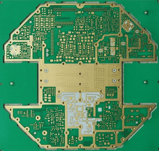
RF PCBs are those boards that operate above 100MHz.
Recently, these PCBs have become more common.
However, in the PCB industry, any board that operates at 2GHz and above is classified as a microwave PCB.
What are the advantages of using RF PCBs?
RF PCBs are highly regarded for their ability to transmit communication signals. This is because of their advanced composite materials.
This is due to their advanced composite materials, which have specific properties in terms of dielectric constant, loss tangent loss, and CTE.
These properties determine that the impedance of high-speed signals when transmitted in the PCB is negligible compared to the impedance in FR4-PCB materials.
Unlike other PCBs, these materials can be stacked and mixed uniformly. This increases performance parameters and reduces production costs.
These boards also exude great stability when operating at high temperatures. This allows the placement of fine-pitch components.
Using low-CTE materials, you can ensure the alignment of multiple layers, including the features they represent in complex PCB layouts.
Are there any limitations when using RF PCB?
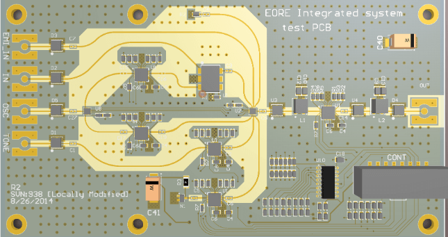
RF PCB design is complex compared to standard PCB.
This is attributed to the fact that several problems may occur when receiving and subsequently transmitting radio signals.
Secondly, a comparison between standard PCB and RF PCB shows that RF PCB signals are sensitive to noise.
Therefore, they require tighter impedance tolerances. Ground planes and larger bend radii are used as a way to control trace impedance.
What are the applications of RF PCB?
Some of the major applications of RF PCB include:
1) Wireless Technology
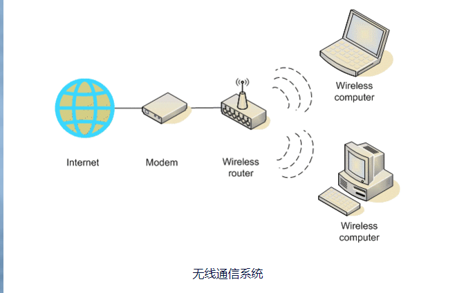
Wireless applications such as TV remote control rely on RF PCB to transmit commands to the TV according to the user’s preferences.
Another example of wireless technology that uses RF PCB is walkie-talkie.
In security operations, security agents are required to reliably receive and transmit information. This is common in the military and police.
2) Smartphones

The popularity and use of smartphones has increased in recent years. These devices rely on various wireless applications.
For example, mobile phone hotspots relay shared information between devices. To effectively relay radio frequencies, these devices rely on RF PCB.
3) Sensors
Sensors are used in various applications today. Some of these include automatic doors and gates.
For such applications to function effectively, sensors are essential. These sensors are developed with RF PCBs for wireless communication.
4) Robotics and Security
Robotics and security systems such as military radars and communication equipment also rely on RF PCB.

Of course, these are some of the main applications for RF PCBs.
7 factors that affect PCB design
- Impedance matching, in controlled impedance RF circuits, when the impedance of the entire trace remains the same, the maximum power transfer from source to load will not be distorted.
This impedance is called the characteristic impedance (Z0) of the trace. The characteristic impedance depends on the geometry of the trace, such as the trace width, the dielectric constant of the PCB material, the thickness of the trace, and the height from the reference ground plane. In order to match these impedances, matching circuits are also designed. - RF board materials, RF PCBs are made of certain materials that meet high-frequency operation requirements. These materials should have low signal loss, remain stable under high-frequency operation, and should be able to absorb a lot of heat.
The dielectric constant (DK), loss tangent (tan8), and coefficient of thermal expansion (CTE) values also need to be consistent over a wide frequency range. The typical values of the dielectric constant of these boards range from 3 to 3.5. For the frequency range of 10-30GHz, the loss tangent values range from 0.0022 to 0.0095. - RF PCB stackup, RF board stackup needs to pay attention to isolation between traces and components, power decoupling, number of layers and arrangement, component placement and other details.
The standard 4-layer RF stackup is shown in the figure above. RF components and traces are placed on the top layer. This layer is followed by the ground layer and the power layer. All non-RF components and traces are filled in the bottom layer. This arrangement provides minimal interference between RF and non-RF components. The direct ground layer provides a minimum path for ground return current. So, in summary, this is a stackup suitable for small RF boards. - RF trace design, RF traces propagate high-frequency signals and are therefore subject to transmission loss and interference issues. The characteristic impedance of these traces is the main concern of designers. In RF boards, traces are treated as transmission lines. The most common types of transmission lines designed are coplanar waveguide (CPWG), microstrip, and stripline.
- Ground plane design, any RF trace or component requires a return path for current to propagate through it. The ground plane is responsible for this. However, the ground plane requires some additional design considerations.
- By design, vias in RF traces should be avoided whenever possible. However, if these cannot be avoided, specific via diameters and lengths must be followed. Vias induce parasitic capacitance in the board. In the case of RF boards, this capacitance affects high-frequency operations.
- Power supply decoupling, for RF boards, noise reduction is critical. At high operating frequencies, these boards become very sensitive to the effects of noise. Therefore, all possible methods are used for noise reduction. One such method is called power supply decoupling.