
Skip to content
Andwin Circuits
  • Home
  • ProductsExpand
    • HDI multilayer PCB
    • Rigid Flex PCB
    • Flex pcb
    • Special PCBExpand
      • High Frequency PCBExpand
        • Rogers RO4350B PCB
        • Rogers RO4003 pcb
        • Rogers RO3003 PCB
        • Rogers 5880 PCB
        • DICLAD 527 PCB
        • Taconic TLX series
        • Taconic TLX-8 RF PCB
        • Taconic TLX-9 RF PCB
      • High speed pcbExpand
        • Megtron 6 High Speed PCB
        • TU-872 SLK Sp High Speed
      • High TG PCBExpand
        • SHENGYI SH260 PCB
        • ISOLA 370HR PCB
        • ISOLA IS410 PCB
        • ISOLA IS420 PCB
      • Heavy copper PCB
      • Copper coin pcb
      • Copper inlay PCB
    • Metal Core PCBExpand
      • Copper core pcb
      • Aluminum PCB
      • 2 Layers Aluminum PCB
      • Direct thermal MCPCB
      • 2 Layers Direct Thermal
    • Ceramic PCBExpand
      • DPC ceramic PCB
      • DBC ceramic PCB
      • Thick film Ceramic PCB
      • Al2O3 Alumina PCB
      • AIN ALN ceramic PCB
      • IGBT Ceramic PCB
  • ServiceExpand
    • PCB Assembly
    • Quick turn PCB assembly
    • PCBA conformal coating
  • IndustryExpand
    • Telecommunication
    • IoT and Wireless
    • Industrial Control
    • Thermal management
    • Power and Energy
    • IC test board
    • Automative
    • Medical
  • CapabilityExpand
    • Rigid PCB
    • Rigid flex PCB
    • Metal core PCB
    • PCB Assembly
  • TechnologyExpand
    • Blogs
    • Via in pad
    • PCB E-test
    • PCB stack up
    • MCPCB panelization
    • Controlled impedance PCB
  • AboutExpand
    • About us
    • Certification
    • Factory Tour
  • Contact
Andwin Circuits
Home / Blogs / metal core pcb reflow profile

metal core pcb reflow profile

ByAlice June 19, 2023June 17, 2024

Metal core PCBs, also known as MCPCBs, are becoming increasingly popular in the electronics
industry due to their superior thermal management capabilities. These boards are designed
with a metal core layer, typically made of aluminum or copper, which helps to dissipate
heat more efficiently than traditional FR4 PCBs. However, the use of metal core PCBs
requires a different reflow profile than standard PCBs. In this article, we will discuss
the reflow profile for metal core PCBs and how to optimize it for the best results.

The reflow process is a critical step in the manufacturing of PCBs. During this process,
the solder paste is melted, and the components are attached to the board. The reflow
profile is a set of parameters that control the temperature and time during the reflow
process. The reflow profile for metal core PCBs is different from that of standard PCBs due
to the metal core layer’s thermal conductivity.
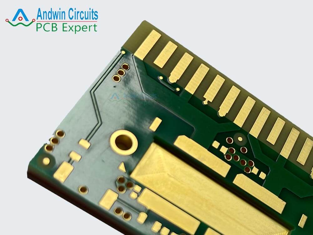
copper coin pcb

The first step in creating a reflow profile for metal core PCBs is to determine the board’s
thermal properties. The thermal conductivity of the metal core layer will affect the heat
transfer during the reflow process. The thermal conductivity of aluminum is around 200
W/mK, while copper is around 400 W/mK. This means that copper core PCBs will require less
time and temperature to reach the desired soldering temperature than aluminum core PCBs.

Once the thermal properties of the board are determined, the next step is to create a
reflow profile that will ensure proper soldering of the components. The reflow profile
consists of several stages, including preheat, soak, reflow, and cooling. Each stage has
specific temperature and time parameters that must be optimized for the specific board
being manufactured.

The preheat stage is the first stage of the reflow process. During this stage, the board is
gradually heated to a temperature that will activate the flux in the solder paste. The
preheat temperature should be set to a level that will not damage the components or the
board. For metal core PCBs, the preheat temperature should be around 150-170°C, depending
on the board’s thermal properties.
GET IN TOUCH!

The soak stage follows the preheat stage. During this stage, the board is held at a
constant temperature for a set amount of time. This allows the solder paste to fully
activate and ensures that all the components reach the same temperature. The soak time for
metal core PCBs should be around 60-90 seconds, depending on the board’s thermal
properties.

The reflow stage is the most critical stage of the reflow process. During this stage, the
board is heated to the soldering temperature, and the solder paste is melted. The reflow
temperature for metal core PCBs should be around 230-250°C, depending on the board’s
thermal properties. The reflow time should be around 30-60 seconds, depending on the
board’s thermal properties and the size of the components.
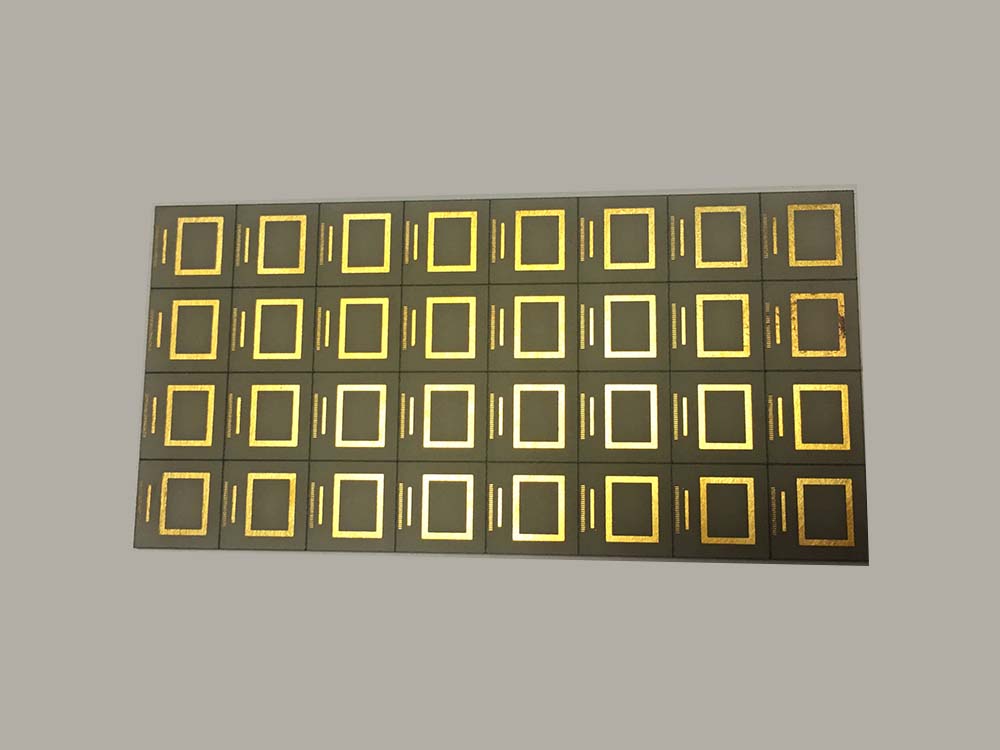
Nitride Aluminum ceramic pcb

The cooling stage is the final stage of the reflow process. During this stage, the board is
cooled down to room temperature. The cooling rate should be slow and steady to prevent
thermal shock and board warping. The cooling rate for metal core PCBs should be around 2-3
°C per second.

In conclusion, metal core PCBs require a different reflow profile than standard PCBs due to
their thermal properties. The reflow profile for metal core PCBs should be optimized to
ensure proper soldering of the components and prevent board damage. By following the
guidelines outlined in this article, manufacturers can create a reflow profile that will
produce high-quality metal core PCBs.

GET IN TOUCH!

Post navigation

Previous Previous
Ceramic fibre grinding brush-Ceramic Brush For PCB
NextContinue
Metal Core PCB Vias: The Ultimate Solution for High-Power LED Applications

Search

Search

Products

  • HDI Multilayer PCB
  • Rigid Flex PCB
  • Flex pcb
  • High Frequency PCB
  • High speed pcb
  • Heavy copper PCB
  • Metal Core PCB
  • Ceramic PCB

Address

Andwin Circuits Co.,Limited
Email: sales@andwinpcb.com
Tel: +86 755 2832 9394
Fax:+86 755 2992  6717
ADD:1-2F-1217,HouDeQun Industrial park,
NanTing RD NO.56,ShaJing,BaoAn,Shenzhen 518104,GuangDong,China

Products

  • HDI Multilayer PCB
  • Rigid Flex PCB
  • Flex pcb
  • High Frequency PCB
  • High speed pcb
  • Heavy copper PCB
  • Metal Core PCB
  • Ceramic PCB

Technology

  • Blogs
  • Via in pad
  • PCB E-test
  • PCB stack up
  • Metal core PCB panelization
  • Controlled impedance PCB

CERTIFICATION

Certification >>


Copyright© 2003 - 2026 Andwin | All Rights Reserved | Powered by Andwin

Scroll to top
  • Home
  • Products
    • HDI multilayer PCB
    • Rigid Flex PCB
    • Flex pcb
    • Special PCB
      • High Frequency PCB
        • Rogers RO4350B PCB
        • Rogers RO4003 pcb
        • Rogers RO3003 PCB
        • Rogers 5880 PCB
        • DICLAD 527 PCB
        • Taconic TLX series
        • Taconic TLX-8 RF PCB
        • Taconic TLX-9 RF PCB
      • High speed pcb
        • Megtron 6 High Speed PCB
        • TU-872 SLK Sp High Speed
      • High TG PCB
        • SHENGYI SH260 PCB
        • ISOLA 370HR PCB
        • ISOLA IS410 PCB
        • ISOLA IS420 PCB
      • Heavy copper PCB
      • Copper coin pcb
      • Copper inlay PCB
    • Metal Core PCB
      • Copper core pcb
      • Aluminum PCB
      • 2 Layers Aluminum PCB
      • Direct thermal MCPCB
      • 2 Layers Direct Thermal
    • Ceramic PCB
      • DPC ceramic PCB
      • DBC ceramic PCB
      • Thick film Ceramic PCB
      • Al2O3 Alumina PCB
      • AIN ALN ceramic PCB
      • IGBT Ceramic PCB
  • Service
    • PCB Assembly
    • Quick turn PCB assembly
    • PCBA conformal coating
  • Industry
    • Telecommunication
    • IoT and Wireless
    • Industrial Control
    • Thermal management
    • Power and Energy
    • IC test board
    • Automative
    • Medical
  • Capability
    • Rigid PCB
    • Rigid flex PCB
    • Metal core PCB
    • PCB Assembly
  • Technology
    • Blogs
    • Via in pad
    • PCB E-test
    • PCB stack up
    • MCPCB panelization
    • Controlled impedance PCB
  • About
    • About us
    • Certification
    • Factory Tour
  • Contact
Search