
Skip to content
Andwin Circuits
  • Home
  • ProductsExpand
    • HDI multilayer PCB
    • Rigid Flex PCB
    • Flex pcb
    • Special PCBExpand
      • High Frequency PCBExpand
        • Rogers RO4350B PCB
        • Rogers RO4003 pcb
        • Rogers RO3003 PCB
        • Rogers 5880 PCB
        • DICLAD 527 PCB
        • Taconic TLX series
        • Taconic TLX-8 RF PCB
        • Taconic TLX-9 RF PCB
      • High speed pcbExpand
        • Megtron 6 High Speed PCB
        • TU-872 SLK Sp High Speed
      • High TG PCBExpand
        • SHENGYI SH260 PCB
        • ISOLA 370HR PCB
        • ISOLA IS410 PCB
        • ISOLA IS420 PCB
      • Heavy copper PCB
      • Copper coin pcb
      • Copper inlay PCB
    • Metal Core PCBExpand
      • Copper core pcb
      • Aluminum PCB
      • 2 Layers Aluminum PCB
      • Direct thermal MCPCB
      • 2 Layers Direct Thermal
    • Ceramic PCBExpand
      • DPC ceramic PCB
      • DBC ceramic PCB
      • Thick film Ceramic PCB
      • Al2O3 Alumina PCB
      • AIN ALN ceramic PCB
      • IGBT Ceramic PCB
  • ServiceExpand
    • PCB Assembly
    • Quick turn PCB assembly
    • PCBA conformal coating
  • IndustryExpand
    • Telecommunication
    • IoT and Wireless
    • Industrial Control
    • Thermal management
    • Power and Energy
    • IC test board
    • Automative
    • Medical
  • CapabilityExpand
    • Rigid PCB
    • Rigid flex PCB
    • Metal core PCB
    • PCB Assembly
  • TechnologyExpand
    • Blogs
    • Via in pad
    • PCB E-test
    • PCB stack up
    • MCPCB panelization
    • Controlled impedance PCB
  • AboutExpand
    • About us
    • Certification
    • Factory Tour
  • Contact
Andwin Circuits
Home / Blogs / Flex pcb gerber files

Flex pcb gerber files

ByGrace July 15, 2023April 1, 2026

Flex PCB gerber files are a set of manufacturing files that contain the information needed to fabricate a flexible printed circuit board (PCB).
Gerber files are used by PCB manufacturers to create the copper traces, pads, and other features on the flexible PCB.

The files include information such as the layer stackup, copper traces, drill holes, and any other design features.
The gerber files are generated by the PCB design software and are typically exported in a standard format that can be read by the manufacturer’s equipment.

The manufacturer uses the gerber files to create the photomasks and other manufacturing tools needed to produce the flex PCB.
It’s important to ensure that the gerber files are accurate and complete to ensure that the final product meets the design specifications.
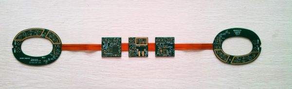
flex pcb high speed

Flex PCBs can be designed for high-speed applications, such as those found in communication systems, data centers, and other electronic devices.
High-speed flex PCBs require careful design considerations to ensure signal integrity and minimize signal loss.

Some of the key design considerations for high-speed flex PCBs include:

1. Impedance control:

High-speed signals require impedance control to ensure that the signal is not reflected or attenuated,
which can lead to signal distortion and errors.

The trace width, spacing, and dielectric constant of the flex PCB material must be carefully selected to achieve the desired impedance.

2. Crosstalk:

High-speed signals can interfere with each other, leading to crosstalk and signal degradation.
Crosstalk can be minimized by increasing the spacing between traces and using shielding techniques.

3. Signal routing:

High-speed signals should be routed as short and direct as possible to minimize signal loss and delay.
The routing should also avoid sharp bends and corners, which can cause signal reflections and distortion.

4. Grounding:

Proper grounding is critical for high-speed flex PCBs.
A solid ground plane should be used to provide a low impedance path for return currents and minimize electromagnetic interference.

5. EMI/RFI shielding:

High-speed flex PCBs may require shielding to prevent electromagnetic interference (EMI) and radio frequency interference (RFI) from affecting the signal quality. Shielding can be achieved through the use of conductive materials or by enclosing the flex PCB in a shielded enclosure.

Overall, designing high-speed flex PCBs requires a deep understanding of signal integrity and the ability to balance design constraints with performance requirements.
GET IN TOUCH!

The benefits of high speed on flexible circuit boards

1. Improved signal integrity:

High-speed signals can experience signal degradation due to factors such as noise, crosstalk, and impedance mismatches.
Flexible circuit boards can help mitigate these issues by providing a more controlled impedance environment, reducing the risk of signal distortion.

2. Increased design flexibility:

Flexible circuit boards can be designed to fit into tight spaces and conform to complex shapes, allowing for more creative and innovative product designs. High-speed capabilities on these boards can further enhance their design flexibility, enabling the creation of more sophisticated and high-performance products.

3. Reduced weight and size:

Flexible circuit boards are typically lighter and thinner than traditional rigid boards, making them ideal for applications where weight and size are critical factors. High-speed capabilities on these boards can help reduce the number of components required, further reducing weight and size.

4. Improved reliability:

Flexible circuit boards are less prone to mechanical stress and vibration, which can cause failures in traditional rigid boards.
High-speed capabilities on these boards can help ensure reliable signal transmission, reducing the risk of product failure.

5. Cost-effective:

Flexible circuit boards can be manufactured in large volumes using automated processes, reducing production costs.
High-speed capabilities on these boards can help reduce the number of components required, further reducing costs.

GET IN TOUCH!

Post navigation

Previous Previous
Flex pcb gold fingers
NextContinue
Flex pcb ground plane

Search

Search

Products

  • HDI Multilayer PCB
  • Rigid Flex PCB
  • Flex pcb
  • High Frequency PCB
  • High speed pcb
  • Heavy copper PCB
  • Metal Core PCB
  • Ceramic PCB

Address

Andwin Circuits Co.,Limited
Email: sales@andwinpcb.com
Tel: +86 755 2832 9394
Fax:+86 755 2992  6717
ADD:1-2F-1217,HouDeQun Industrial park,
NanTing RD NO.56,ShaJing,BaoAn,Shenzhen 518104,GuangDong,China

Products

  • HDI Multilayer PCB
  • Rigid Flex PCB
  • Flex pcb
  • High Frequency PCB
  • High speed pcb
  • Heavy copper PCB
  • Metal Core PCB
  • Ceramic PCB

Technology

  • Blogs
  • Via in pad
  • PCB E-test
  • PCB stack up
  • Metal core PCB panelization
  • Controlled impedance PCB

CERTIFICATION

Certification >>


Copyright© 2003 - 2026 Andwin | All Rights Reserved | Powered by Andwin

Scroll to top
  • Home
  • Products
    • HDI multilayer PCB
    • Rigid Flex PCB
    • Flex pcb
    • Special PCB
      • High Frequency PCB
        • Rogers RO4350B PCB
        • Rogers RO4003 pcb
        • Rogers RO3003 PCB
        • Rogers 5880 PCB
        • DICLAD 527 PCB
        • Taconic TLX series
        • Taconic TLX-8 RF PCB
        • Taconic TLX-9 RF PCB
      • High speed pcb
        • Megtron 6 High Speed PCB
        • TU-872 SLK Sp High Speed
      • High TG PCB
        • SHENGYI SH260 PCB
        • ISOLA 370HR PCB
        • ISOLA IS410 PCB
        • ISOLA IS420 PCB
      • Heavy copper PCB
      • Copper coin pcb
      • Copper inlay PCB
    • Metal Core PCB
      • Copper core pcb
      • Aluminum PCB
      • 2 Layers Aluminum PCB
      • Direct thermal MCPCB
      • 2 Layers Direct Thermal
    • Ceramic PCB
      • DPC ceramic PCB
      • DBC ceramic PCB
      • Thick film Ceramic PCB
      • Al2O3 Alumina PCB
      • AIN ALN ceramic PCB
      • IGBT Ceramic PCB
  • Service
    • PCB Assembly
    • Quick turn PCB assembly
    • PCBA conformal coating
  • Industry
    • Telecommunication
    • IoT and Wireless
    • Industrial Control
    • Thermal management
    • Power and Energy
    • IC test board
    • Automative
    • Medical
  • Capability
    • Rigid PCB
    • Rigid flex PCB
    • Metal core PCB
    • PCB Assembly
  • Technology
    • Blogs
    • Via in pad
    • PCB E-test
    • PCB stack up
    • MCPCB panelization
    • Controlled impedance PCB
  • About
    • About us
    • Certification
    • Factory Tour
  • Contact
Search