
Skip to content
Andwin Circuits
  • Home
  • ProductsExpand
    • HDI multilayer PCB
    • Rigid Flex PCB
    • Flex pcb
    • Special PCBExpand
      • High Frequency PCBExpand
        • Rogers RO4350B PCB
        • Rogers RO4003 pcb
        • Rogers RO3003 PCB
        • Rogers 5880 PCB
        • DICLAD 527 PCB
        • Taconic TLX series
        • Taconic TLX-8 RF PCB
        • Taconic TLX-9 RF PCB
      • High speed pcbExpand
        • Megtron 6 High Speed PCB
        • TU-872 SLK Sp High Speed
      • High TG PCBExpand
        • SHENGYI SH260 PCB
        • ISOLA 370HR PCB
        • ISOLA IS410 PCB
        • ISOLA IS420 PCB
      • Heavy copper PCB
      • Copper coin pcb
      • Copper inlay PCB
    • Metal Core PCBExpand
      • Copper core pcb
      • Aluminum PCB
      • 2 Layers Aluminum PCB
      • Direct thermal MCPCB
      • 2 Layers Direct Thermal
    • Ceramic PCBExpand
      • DPC ceramic PCB
      • DBC ceramic PCB
      • Thick film Ceramic PCB
      • Al2O3 Alumina PCB
      • AIN ALN ceramic PCB
      • IGBT Ceramic PCB
  • ServiceExpand
    • PCB Assembly
    • Quick turn PCB assembly
    • PCBA conformal coating
  • IndustryExpand
    • Telecommunication
    • IoT and Wireless
    • Industrial Control
    • Thermal management
    • Power and Energy
    • IC test board
    • Automative
    • Medical
  • CapabilityExpand
    • Rigid PCB
    • Rigid flex PCB
    • Metal core PCB
    • PCB Assembly
  • TechnologyExpand
    • Blogs
    • Via in pad
    • PCB E-test
    • PCB stack up
    • MCPCB panelization
    • Controlled impedance PCB
  • AboutExpand
    • About us
    • Certification
    • Factory Tour
  • Contact
Andwin Circuits
Home / PCB Impedance Design

PCB Impedance Design

ByGrace November 22, 2024November 21, 2024

1.What is impedance?

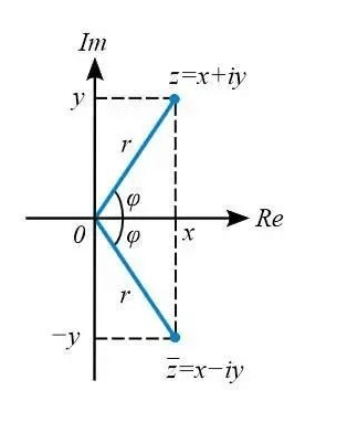
    In electrical engineering, the resistance to the current in a circuit is often called impedance. The unit of impedance is ohm, usually represented by Z, which is a complex number:

    Z= R i( ωL–1/(ωC))

    Specifically, impedance can be divided into two parts, resistance (real part) and reactance (imaginary part).

    Among them, reactance includes capacitive reactance and inductive reactance. The current resistance caused by capacitance is called capacitive reactance, and the current resistance caused by inductance is called inductive reactance.
    2.Ideal model of impedance matching

      Most RF engineers have encountered the problem of impedance matching. Generally speaking, the purpose of impedance matching is to ensure the effective transmission of signals or energy from the “signal source” to the “load”.

      The most ideal model is of course to hope that the output impedance of the Source end is 50 ohms, the impedance of the transmission line is 50 ohms, and the input impedance of the Load end is also 50 ohms. This is the most ideal.
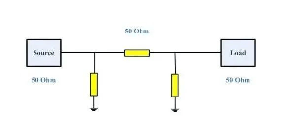
      However, the actual situation is: the source impedance will not be 50ohm, and the load impedance will not be 50ohm either. At this time, several impedance matching circuits are needed.

      The matching circuit is composed of inductors and capacitors. At this time, we need to use capacitors and inductors to debug the impedance matching circuit to achieve the best RF performance.

      Contact us for PCB quote now |

      3.Impedance matching method

        There are two main methods of impedance matching, one is to change the impedance, and the other is to adjust the transmission line.

        Changing the impedance is to adjust the load impedance value through the series and parallel connection of capacitors, inductors and loads to achieve source and load impedance matching.

        Adjusting the transmission line is to lengthen the distance between the source and the load, and adjust the impedance to zero with capacitors and inductors.

        At this time, the signal will not be emitted, and the energy can be absorbed by the load.

        In high-speed PCB wiring, the routing impedance of digital signals is generally designed to be 50 ohms. It is generally stipulated that the baseband of coaxial cable is 50 ohms, the frequency band is 75 ohms, and the twisted pair (differential) is 85-100 ohms.

        4.Application of Smith chart in RF matching circuit debugging

          The Smith chart can reflect the following information: impedance parameter Z, admittance parameter Y, quality factor Q, reflection coefficient, standing wave coefficient, noise factor, gain, stability factor, power, efficiency, frequency information and other impedance parameters.
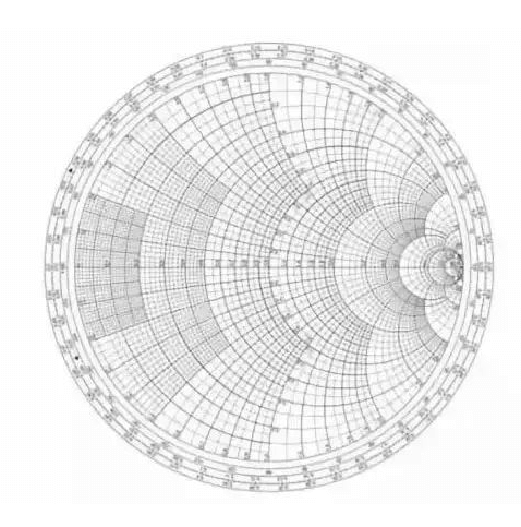
          The composition principle of the impedance circle diagram is to use the one-to-one correspondence between the input impedance and the voltage reflection coefficient to express the normalized input impedance in the reflection coefficient polar coordinate system. Its characteristics are summarized as follows:

          The upper semicircle impedance is inductive reactance, and the lower semicircle impedance is capacitive reactance;
          The real axis is pure resistance, and the unit circle is pure reactance;
          The right half of the real axis is all voltage antinode points (except open circuit points), and the left half is all voltage wave nodes (except short circuit points);
          Matching point (1, 0), open circuit point (∞, ∞) and short circuit point (0, 0);
          Two special circles: the largest is the pure reactance circle, and the one tangent to the imaginary axis is the matching circle;
          Two rotation directions: counterclockwise rotation means moving toward the load, and clockwise rotation means moving toward the wave source.

          Contact us for PCB quote now |

          The admittance circle diagram and the impedance circle diagram are centrally symmetrical to each other.

          The same circle diagram can be used as an impedance circle diagram or an admittance circle diagram. However, when performing each operation, if it is used as an impedance circle diagram, it cannot be used as an admittance circle diagram.

          The Smith chart can show some very interesting features:

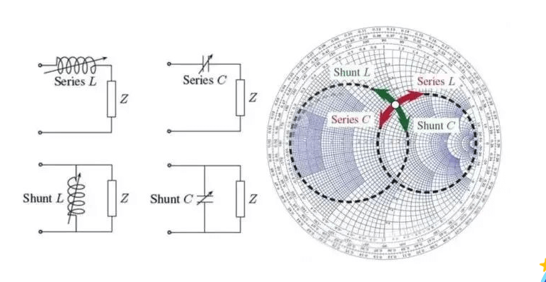
          When a variable inductor/capacitor is connected in series or in parallel before the load, the circuit diagram is shown in the 4 figures on the left of the figure below, and several curves on the right side of the Smith chart will be obtained.

          Corresponding to the Smith impedance circle and admittance circle, their movement trajectories are as follows:

          When using the Smith impedance circle, the series inductor rotates clockwise and the series capacitor rotates counterclockwise;
          When using the Smith admittance circle, the parallel inductor rotates counterclockwise and the parallel capacitor rotates clockwise.
          Contact us for PCB quote now |
          Post Tags: #https://youtu.be/Nc-ErDyoRl4?si=Gq9oRs2FgarR688w

          Post navigation

          Previous Previous
          Exploring PCB and PCBA Technologies for Modern Electronics
          NextContinue
          Will PCB expire? Should I bake it after it expires?

          Search

          Search

          Products

          • HDI Multilayer PCB
          • Rigid Flex PCB
          • Flex pcb
          • High Frequency PCB
          • High speed pcb
          • Heavy copper PCB
          • Metal Core PCB
          • Ceramic PCB

          Address

          Andwin Circuits Co.,Limited
          Email: sales@andwinpcb.com
          Tel: +86 755 2832 9394
          Fax:+86 755 2992  6717
          ADD:1-2F-1217,HouDeQun Industrial park,
          NanTing RD NO.56,ShaJing,BaoAn,Shenzhen 518104,GuangDong,China

          Products

          • HDI Multilayer PCB
          • Rigid Flex PCB
          • Flex pcb
          • High Frequency PCB
          • High speed pcb
          • Heavy copper PCB
          • Metal Core PCB
          • Ceramic PCB

          Technology

          • Blogs
          • Via in pad
          • PCB E-test
          • PCB stack up
          • Metal core PCB panelization
          • Controlled impedance PCB

          CERTIFICATION

          Certification >>


          Copyright© 2003 - 2026 Andwin | All Rights Reserved | Powered by Andwin

          Scroll to top
          • Home
          • Products
            • HDI multilayer PCB
            • Rigid Flex PCB
            • Flex pcb
            • Special PCB
              • High Frequency PCB
                • Rogers RO4350B PCB
                • Rogers RO4003 pcb
                • Rogers RO3003 PCB
                • Rogers 5880 PCB
                • DICLAD 527 PCB
                • Taconic TLX series
                • Taconic TLX-8 RF PCB
                • Taconic TLX-9 RF PCB
              • High speed pcb
                • Megtron 6 High Speed PCB
                • TU-872 SLK Sp High Speed
              • High TG PCB
                • SHENGYI SH260 PCB
                • ISOLA 370HR PCB
                • ISOLA IS410 PCB
                • ISOLA IS420 PCB
              • Heavy copper PCB
              • Copper coin pcb
              • Copper inlay PCB
            • Metal Core PCB
              • Copper core pcb
              • Aluminum PCB
              • 2 Layers Aluminum PCB
              • Direct thermal MCPCB
              • 2 Layers Direct Thermal
            • Ceramic PCB
              • DPC ceramic PCB
              • DBC ceramic PCB
              • Thick film Ceramic PCB
              • Al2O3 Alumina PCB
              • AIN ALN ceramic PCB
              • IGBT Ceramic PCB
          • Service
            • PCB Assembly
            • Quick turn PCB assembly
            • PCBA conformal coating
          • Industry
            • Telecommunication
            • IoT and Wireless
            • Industrial Control
            • Thermal management
            • Power and Energy
            • IC test board
            • Automative
            • Medical
          • Capability
            • Rigid PCB
            • Rigid flex PCB
            • Metal core PCB
            • PCB Assembly
          • Technology
            • Blogs
            • Via in pad
            • PCB E-test
            • PCB stack up
            • MCPCB panelization
            • Controlled impedance PCB
          • About
            • About us
            • Certification
            • Factory Tour
          • Contact
          Search