
Simulation of EMC/EMI in PCB design
As the density of electronic devices on PCB boards increases, the routing becomes narrower, the routing density increases, and the frequency of signals increases, EMC (electromagnetic compatibility) and EMI (electromagnetic interference) problems are inevitably introduced, so the electromagnetic compatibility analysis and application of electronic products are very important.
However, the general situation at home and abroad is that compared with IC design, EMC analysis and simulation in the PCB design process is a weak link. At the same time, EMC simulation analysis is gradually playing an increasingly important role in PCB design.
Analysis targets of EMC/EMI in PCB design Signal integrity analysis includes reflection analysis of the same signal on the same wiring network, impedance matching analysis, signal overshoot analysis, signal timing analysis, etc.;
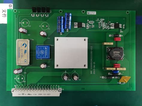
crosstalk analysis between different signals on adjacent wiring networks.
In signal integrity analysis, the physical topology of the wiring network, the dielectric properties and dielectric constant of the PCB dielectric layer, and the electrical properties of each wiring layer must also be considered. There are now international standards for suppressing EMI in electronic equipment and instruments, collectively referred to as electromagnetic compatibility (EMC) standards.
They can be used as rules for PCB designers to suppress electromagnetic radiation and interference when wiring and laying out. For military electronic product designers, the standards will be stricter and more demanding. For systems composed of multiple PCB boards connected by a bus, it is also necessary to analyze the electromagnetic compatibility performance between different PCB boards and the EMC/EMI performance of interface circuits and connectors.
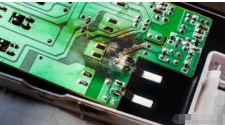
EMC/EMI simulation requires the use of simulation models.
EMC/EMI analysis requires understanding the electrical characteristics of the components used before better simulation can be performed. Currently, IBIS and SPICE models are more widely used. IBIS (I/O Buffer Interface Specification), also known as ANSI/EIA-656, is a model that quickly and accurately describes the electrical performance of I/O buffers based on V/I curves, obtained through measurement or circuit simulation.
In 1990, INTEL took the lead and jointly formulated the industry standard of IBIS V1.0 with several well-known semiconductor manufacturers. After continuous improvement and development, it was updated to IBIS V3.0 in 1997. Now this standard has been supported by hundreds of semiconductor manufacturers such as NS, Motorola, TI, IDT, Xilinx, Siemens, Cypress, VLSI, etc. At the same time, RDA companies such as Cadence, Mentor, Incases, Zuken-Redac, etc. have also added IBIS function modules in their respective software.
IBIS file is a text file that describes the behavioral information generated in a standard software format to illustrate the analog electrical characteristics of IC. The SPICE model of IC is a trade secret of each semiconductor manufacturer and is protected by intellectual property rights, while the IBIS model is data that is completely open to users, so designers can easily obtain the IBIS model. Of course, if there is a SPICE model, the IBIS model can be generated from the SPICE model. At present, IBIS models can generally be obtained from device manufacturers.
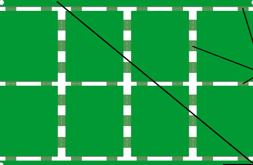
Apply EMC/EMI simulation to improve the quality of PCB design.
After the PCB layout and routing is completed, the circuit design is analyzed and simulated for EMC/EMI before the GERBER file is made into a circuit board. At the same time, the signal strength, delay and other characteristics are analyzed according to the dynamic working frequency of the actual circuit. If the designed PCB contains an interface with the outside, a heat sink is added to the IC or the circuit itself has high power consumption, further simulation and analysis of electromagnetic radiation must be performed. For high-speed circuits, it is necessary to analyze the transmission line distribution parameters of the wiring network.
EDA developers have gradually realized the needs of users in the field of EMC/EMI simulation.
Germany’s INCASES company provides designers with EMC/EMI simulation analysis software package EMC-WORKBENCH, becoming a leader in the industry and hosting IEEE seminars on EMC/EMI many times. EMC-WORKBENCH can meet the urgent needs of circuit designers in terms of electromagnetic compatibility, improve the process of PCB design, and simplify many complicated tasks in the later hardware debugging.
At the same time, the EMC/EMI problem inside the IC should also be fully considered. At present, most chip manufacturers will handle the EMC/EMI problem inside the IC. However, designers should also pay attention to possible problems in chips and solve EMC/EMI on the board to the extreme.
Electronic engineers can use simulation tools and effectively integrate design experience to better improve product quality and reliability。