
Skip to content
Andwin Circuits
  • Home
  • ProductsExpand
    • HDI multilayer PCB
    • Rigid Flex PCB
    • Flex pcb
    • Special PCBExpand
      • High Frequency PCBExpand
        • Rogers RO4350B PCB
        • Rogers RO4003 pcb
        • Rogers RO3003 PCB
        • Rogers 5880 PCB
        • DICLAD 527 PCB
        • Taconic TLX series
        • Taconic TLX-8 RF PCB
        • Taconic TLX-9 RF PCB
      • High speed pcbExpand
        • Megtron 6 High Speed PCB
        • TU-872 SLK Sp High Speed
      • High TG PCBExpand
        • SHENGYI SH260 PCB
        • ISOLA 370HR PCB
        • ISOLA IS410 PCB
        • ISOLA IS420 PCB
      • Heavy copper PCB
      • Copper coin pcb
      • Copper inlay PCB
    • Metal Core PCBExpand
      • Copper core pcb
      • Aluminum PCB
      • 2 Layers Aluminum PCB
      • Direct thermal MCPCB
      • 2 Layers Direct Thermal
    • Ceramic PCBExpand
      • DPC ceramic PCB
      • DBC ceramic PCB
      • Thick film Ceramic PCB
      • Al2O3 Alumina PCB
      • AIN ALN ceramic PCB
      • IGBT Ceramic PCB
  • ServiceExpand
    • PCB Assembly
    • Quick turn PCB assembly
    • PCBA conformal coating
  • IndustryExpand
    • Telecommunication
    • IoT and Wireless
    • Industrial Control
    • Thermal management
    • Power and Energy
    • IC test board
    • Automative
    • Medical
  • CapabilityExpand
    • Rigid PCB
    • Rigid flex PCB
    • Metal core PCB
    • PCB Assembly
  • TechnologyExpand
    • Blogs
    • Via in pad
    • PCB E-test
    • PCB stack up
    • MCPCB panelization
    • Controlled impedance PCB
  • AboutExpand
    • About us
    • Certification
    • Factory Tour
  • Contact
Andwin Circuits
Home / How to improve wiring efficiency in PCB design

How to improve wiring efficiency in PCB design

ByGrace January 18, 2025March 31, 2026

Wiring is an extremely important part of PCB design, which will directly affect the performance of the PCB board. In the PCB design process, different layout engineers have their own understanding of layout, but all layout engineers are consistent in how to improve the efficiency of wiring, which can not only save the development cycle of the project for customers, but also maximize the quality and cost. The following is the general design process and steps.

1.Determine the number of layers of the PCB

    The size of the circuit board and the number of wiring layers need to be determined at the beginning of the design. If the design requires the use of high-density ball grid array (BGA) components, the minimum number of wiring layers required for the wiring of these devices must be considered. The number of wiring layers and the stack-up method will directly affect the wiring and impedance of the printed line. The size of the board helps to determine the stack-up method and the width of the printed line to achieve the desired design effect.

    2.Design rules and restrictions

      The automatic wiring tool itself does not know what it should do. To complete the wiring task, the wiring tool needs to work under the correct rules and restrictions. Different signal lines have different wiring requirements. All signal lines with special requirements must be classified, and different design classifications are also different. Each signal class should have a priority. The higher the priority, the stricter the rules. The rules involve the width of the printed line, the maximum number of vias, parallelism, the mutual influence between signal lines, and the restrictions of the layer. These rules have a great impact on the performance of the wiring tool. Careful consideration of design requirements is an important step in successful wiring.
      Contact us for PCB quote now |

      3.Component layout

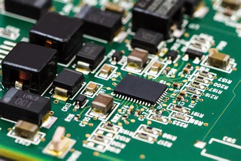
        To optimize the assembly process, design for manufacturability (DFM) rules will restrict component layout. If the assembly department allows component movement, the circuit can be properly optimized to facilitate automatic wiring. The defined rules and constraints will affect the layout design.
        Zhongguancun Yuankun Intelligent Manufacturing Factory is committed to providing customers with one-stop online electronic component procurement services, providing thousands of electronic component procurement, price inquiry and transactions, ensuring that all components are purchased from the original factory or agent’s regular channels, and ensuring original authentic products. It is a professional electronic component procurement website in China.

        4.Fan-out design

          During the fan-out design stage, in order to enable the automatic wiring tool to connect the component pins, each pin of the surface mount device should have at least one via so that the circuit board can perform inner layer connections, online testing (ICT) and circuit reprocessing when more connections are needed.

          In order to make the automatic wiring tool most efficient, it is necessary to use the largest via size and printed wire as much as possible, and the spacing is set to 50mil. It is ideal to use the via type that maximizes the number of wiring paths. When designing fan-out, consider the issue of online circuit testing. Test fixtures can be expensive and are usually ordered when they are about to be put into full production. It is too late to consider adding nodes to achieve 100% testability at this time.
          5.Manual wiring and processing of key signals

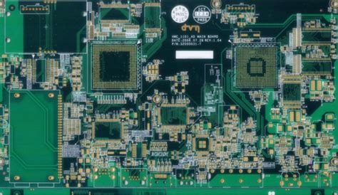
            Although this article mainly discusses automatic wiring, manual wiring is an important process in printed circuit board design now and in the future. Manual wiring helps automatic wiring tools complete wiring work. No matter how many key signals there are, these signals should be routed first, either manually or in combination with automatic wiring tools. Key signals usually require careful circuit design to achieve the desired performance. After the wiring is completed, the relevant engineers will check the wiring of these signals, which is a relatively easy process. After the inspection, these lines are fixed, and then the remaining signals are automatically routed.

            6.Automatic wiring

              For the routing of key signals, it is necessary to consider controlling some electrical parameters during routing, such as reducing distributed inductance and EMC, etc., and the routing of other signals is similar. All EDA manufacturers will provide a method to control these parameters. After understanding the input parameters of the automatic wiring tool and the impact of the input parameters on the wiring, the quality of automatic wiring can be guaranteed to a certain extent.

              7.Appearance of the circuit board

                Previous designs often paid attention to the visual effect of the circuit board, but now it is different. The circuit board designed automatically is not more beautiful than the manually designed one, but it can meet the specified requirements in terms of electronic characteristics, and the complete performance of the design is guaranteed.
                For layout engineers, whether their skills are good or not should not be judged only by the number of layers and speed. Only when the conditions such as the number of components and signal speed are equivalent, can they complete the design with a PCB board with the smaller area, fewer layers and lower cost, and can ensure good performance and aesthetics, and they are masters.

                Contact us for PCB quote now |
                Post Tags: #aluminum clad pcb#aluminum core pcb#aluminum core pcb led#aluminum pcb#assemble pcb

                Post navigation

                Previous Previous
                PCB Design Skills for Switching Power Supply
                NextContinue
                Advancements in Flex PCB SMT Assembly Techniques and Benefits

                Search

                Search

                Products

                • HDI Multilayer PCB
                • Rigid Flex PCB
                • Flex pcb
                • High Frequency PCB
                • High speed pcb
                • Heavy copper PCB
                • Metal Core PCB
                • Ceramic PCB

                Address

                Andwin Circuits Co.,Limited
                Email: sales@andwinpcb.com
                Tel: +86 755 2832 9394
                Fax:+86 755 2992  6717
                ADD:1-2F-1217,HouDeQun Industrial park,
                NanTing RD NO.56,ShaJing,BaoAn,Shenzhen 518104,GuangDong,China

                Products

                • HDI Multilayer PCB
                • Rigid Flex PCB
                • Flex pcb
                • High Frequency PCB
                • High speed pcb
                • Heavy copper PCB
                • Metal Core PCB
                • Ceramic PCB

                Technology

                • Blogs
                • Via in pad
                • PCB E-test
                • PCB stack up
                • Metal core PCB panelization
                • Controlled impedance PCB

                CERTIFICATION

                Certification >>


                Copyright© 2003 - 2026 Andwin | All Rights Reserved | Powered by Andwin

                Scroll to top
                • Home
                • Products
                  • HDI multilayer PCB
                  • Rigid Flex PCB
                  • Flex pcb
                  • Special PCB
                    • High Frequency PCB
                      • Rogers RO4350B PCB
                      • Rogers RO4003 pcb
                      • Rogers RO3003 PCB
                      • Rogers 5880 PCB
                      • DICLAD 527 PCB
                      • Taconic TLX series
                      • Taconic TLX-8 RF PCB
                      • Taconic TLX-9 RF PCB
                    • High speed pcb
                      • Megtron 6 High Speed PCB
                      • TU-872 SLK Sp High Speed
                    • High TG PCB
                      • SHENGYI SH260 PCB
                      • ISOLA 370HR PCB
                      • ISOLA IS410 PCB
                      • ISOLA IS420 PCB
                    • Heavy copper PCB
                    • Copper coin pcb
                    • Copper inlay PCB
                  • Metal Core PCB
                    • Copper core pcb
                    • Aluminum PCB
                    • 2 Layers Aluminum PCB
                    • Direct thermal MCPCB
                    • 2 Layers Direct Thermal
                  • Ceramic PCB
                    • DPC ceramic PCB
                    • DBC ceramic PCB
                    • Thick film Ceramic PCB
                    • Al2O3 Alumina PCB
                    • AIN ALN ceramic PCB
                    • IGBT Ceramic PCB
                • Service
                  • PCB Assembly
                  • Quick turn PCB assembly
                  • PCBA conformal coating
                • Industry
                  • Telecommunication
                  • IoT and Wireless
                  • Industrial Control
                  • Thermal management
                  • Power and Energy
                  • IC test board
                  • Automative
                  • Medical
                • Capability
                  • Rigid PCB
                  • Rigid flex PCB
                  • Metal core PCB
                  • PCB Assembly
                • Technology
                  • Blogs
                  • Via in pad
                  • PCB E-test
                  • PCB stack up
                  • MCPCB panelization
                  • Controlled impedance PCB
                • About
                  • About us
                  • Certification
                  • Factory Tour
                • Contact
                Search