
Understanding mounting holes in PCB design:A Comprehensive guide
Printed Circuit Boards (PCBs) are the backbone of modern electronics, providing the necessary platform for electrical components to connect and function as intended. One critical aspect of PCB design that often goes unnoticed but is essential for the overall functionality and durability of the board is the inclusion of mounting holes. Mounting holes are strategically placed openings in the PCB that allow the board to be securely attached to a chassis, enclosure, or other supporting structures. This article delves into the importance of mounting holes, their design considerations, types, and best practices for incorporating them into PCB layouts.
1. The Importance of Mounting Holes in PCB Design
Mounting holes serve several vital functions in PCB design:
- Mechanical Stability: Mounting holes ensure that the PCB remains firmly in place, preventing movement or vibration that could lead to mechanical stress or damage to the components.
- Heat Dissipation: In some cases, mounting holes can be used to attach heat sinks or other cooling mechanisms, aiding in the thermal management of the board.
- Electrical Grounding: Mounting holes can also serve as grounding points, providing a low-impedance path to the ground plane, which is crucial for reducing electromagnetic interference (EMI) and ensuring signal integrity.
- Ease of Assembly: Properly placed mounting holes facilitate the assembly process, making it easier to align and secure the PCB within its enclosure or chassis.
2. Types of Mounting Holes
There are several types of mounting holes, each serving different purposes based on the specific requirements of the PCB and its application:
- Through-Hole Mounting Holes: These are the most common type of mounting holes, extending through the entire thickness of the PCB. They are typically used with screws or bolts to secure the board to a chassis or enclosure.
- Non-Plated Mounting Holes: These holes are not plated with conductive material, making them suitable for applications where electrical isolation is required. They are often used when the mounting hardware should not be electrically connected to the PCB.
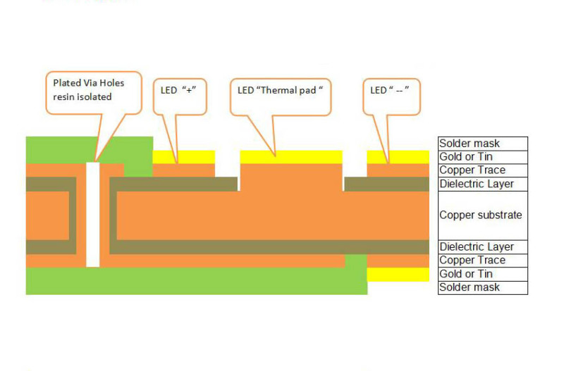
- Plated Mounting Holes: These holes are plated with a conductive material, such as copper, and are often used when the mounting hardware needs to be electrically connected to the PCB, such as for grounding purposes.
- Countersunk Mounting Holes: These holes are designed to accommodate countersunk screws, allowing the screw head to sit flush with or below the surface of the PCB. This is useful in applications where a low profile is required.
- Threaded Mounting Holes: These holes have internal threads, allowing screws to be directly threaded into the PCB. This eliminates the need for nuts on the opposite side of the board, simplifying the assembly process.
3. Design Considerations for Mounting Holes
When designing mounting holes for a PCB, several factors must be taken into account to ensure optimal performance and reliability:
- Hole Size and Placement: The size of the mounting holes should be chosen based on the diameter of the screws or bolts that will be used. The placement of the holes should be carefully considered to ensure even distribution of mechanical stress and to avoid interference with components or traces.
- Clearance and Keep-Out Areas: It is essential to maintain adequate clearance around mounting holes to prevent short circuits or damage to nearby components. Keep-out areas should be defined in the PCB layout to ensure that no traces or components are placed too close to the holes.
- Material and Thickness: The material and thickness of the PCB can affect the strength and durability of the mounting holes. Thicker boards may require larger or reinforced holes to handle the increased mechanical stress.
- Thermal Considerations: If the mounting holes are intended to aid in heat dissipation, their design should take into account the thermal conductivity of the materials used and the placement of heat-generating components.
- Electrical Considerations: For plated mounting holes used for grounding, it is important to ensure a low-impedance connection to the ground plane. This may involve using multiple vias or additional copper pour around the holes.
4. Best Practices for Incorporating Mounting Holes
To ensure that mounting holes are effectively integrated into the PCB design, the following best practices should be followed:
- Early Planning: Mounting holes should be considered early in the design process, ideally during the initial layout phase. This allows for proper placement and avoids last-minute adjustments that could compromise the design.
- Use of CAD Tools: Modern PCB design software often includes tools for automatically generating mounting holes based on predefined templates or user-defined parameters. Utilizing these tools can save time and reduce the risk of errors.
- Prototyping and Testing: Before finalizing the design, it is advisable to create a prototype and test the mounting holes under real-world conditions. This can help identify any issues with mechanical stability, thermal performance, or electrical grounding.
- Documentation: Proper documentation of the mounting hole specifications, including size, placement, and any special requirements, is essential for ensuring consistency during manufacturing and assembly.
- Collaboration with Mechanical Engineers: In many cases, the design of mounting holes requires close collaboration with mechanical engineers to ensure that the PCB will fit securely within the intended enclosure or chassis. This collaboration can help avoid misalignment or interference issues.
5. Common Challenges and Solutions
Despite careful planning, designers may encounter challenges when incorporating mounting holes into their PCB designs. Some common issues and their solutions include:
- Misalignment with Enclosure: If the mounting holes do not align with the holes in the enclosure, the PCB may not fit properly. This can be avoided by using precise measurements and coordinating with the mechanical design team.
- Insufficient Clearance: If there is not enough clearance around the mounting holes, nearby components or traces may be damaged during assembly. This can be mitigated by defining adequate keep-out areas and using design rule checks (DRC) to identify potential issues.
- Weak Mechanical Support: If the mounting holes are too small or not reinforced, they may not provide sufficient mechanical support. This can be addressed by using larger holes, adding reinforcement, or using additional mounting hardware.
- Electrical Noise: If plated mounting holes are used for grounding, improper design can lead to electrical noise or interference. This can be minimized by ensuring a low-impedance connection to the ground plane and using multiple vias if necessary.
6. Conclusion
Mounting holes are a critical yet often overlooked aspect of PCB design. They play a vital role in ensuring the mechanical stability, thermal management, and electrical performance of the board. By understanding the different types of mounting holes, considering key design factors, and following best practices, designers can effectively incorporate mounting holes into their PCB layouts, resulting in more reliable and durable electronic products. As with any aspect of PCB design, careful planning, collaboration, and testing are essential to achieving optimal results.