
Shielding Can Design in PCB Design: Principles, Techniques, and Best Practices
Abstract
In modern electronic circuits, electromagnetic interference (EMI) and radio frequency interference (RFI) are critical challenges that can degrade signal integrity and system performance. Shielding cans (also known as EMI shields or RF shields) are widely used in printed circuit board (PCB) designs to mitigate these issues. This article explores the fundamentals of shielding can design, including material selection, structural considerations, grounding techniques, and manufacturing best practices. By implementing effective shielding strategies, engineers can enhance electromagnetic compatibility (EMC) and ensure reliable operation of electronic devices.
1. Introduction
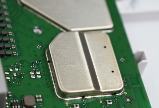
With the increasing complexity and miniaturization of electronic devices, managing electromagnetic interference has become a critical aspect of PCB design. Shielding cans are metallic enclosures placed over sensitive components or circuit sections to block EMI/RFI emissions and prevent external interference. Proper shielding design is essential for compliance with regulatory standards (e.g., FCC, CE) and ensuring optimal performance in applications such as wireless communication, medical devices, and automotive electronics.
2. Why Use Shielding Cans?
Shielding cans serve multiple purposes in PCB design:
- EMI/RFI Suppression: They contain electromagnetic radiation from high-frequency components (e.g., oscillators, RF modules).
- Signal Integrity Protection: They prevent crosstalk and noise coupling between adjacent circuits.
- Thermal Management: Some shielding designs also aid in heat dissipation.
- Mechanical Protection: They safeguard delicate components from physical damage.
Without proper shielding, electronic devices may suffer from degraded performance, increased bit error rates, or even regulatory non-compliance.
3. Key Design Considerations for Shielding Cans
3.1 Material Selection
The choice of shielding material depends on factors such as frequency range, mechanical strength, and cost:
- Copper: Excellent conductivity and solderability, ideal for high-frequency applications.
- Aluminum: Lightweight and cost-effective, but harder to solder.
- Nickel Silver: Corrosion-resistant and durable, often used in harsh environments.
- Ferromagnetic Materials: Effective for low-frequency magnetic shielding.
3.2 Shielding Can Structure
The design of the shielding can affects its effectiveness:
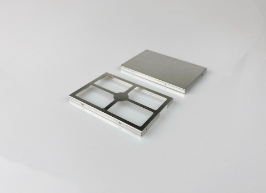
- One-Piece vs. Two-Piece Designs: One-piece shields are simpler but harder to rework, while two-piece designs (frame + lid) allow easier access.
- Aperture and Ventilation: Small openings may be necessary for thermal management but can compromise shielding effectiveness.
- Height and Clearance: The shield should provide sufficient space for components while minimizing air gaps.
3.3 Grounding Techniques
Proper grounding is crucial for effective shielding:
- Low-Impedance Connections: Use multiple grounding vias or a solid ground plane beneath the shield.
- Continuous Seam Welding: Ensures minimal gaps in the shield’s conductive path.
- Avoiding Ground Loops: Ensure the shield is connected to a single reference ground to prevent noise coupling.
3.4 Manufacturing and Assembly Considerations
- Solder vs. Snap-On Shields: Soldered shields provide better EMI sealing, while snap-on shields allow reworkability.
- Pick-and-Place Compatibility: Shielding cans should not interfere with automated PCB assembly processes.
- Thermal Expansion Mismatch: Choose materials that match the PCB’s thermal properties to avoid warping.
4. Simulation and Testing of Shielding Effectiveness
Before finalizing a shielding design, engineers should perform:
- EMI Simulation: Tools like CST Microwave Studio or ANSYS HFSS can predict shielding performance.
- Near-Field and Far-Field Testing: Validates real-world EMI suppression.
- Shielding Effectiveness (SE) Measurement: Quantifies attenuation in decibels (dB).
5. Common Pitfalls and How to Avoid Them
- Insufficient Grounding: Poor grounding reduces shielding effectiveness.
- Excessive Apertures: Large or numerous openings can leak EMI.
- Mechanical Stress: Improperly designed shields may damage components during assembly.
- Over-Shielding: Unnecessary shielding increases cost and weight without significant benefits.
6. Future Trends in Shielding Technology
- 3D-Printed Shields: Custom geometries for complex PCB layouts.
- Conductive Polymers: Lightweight alternatives to metal shields.
- Integrated Shielding in IC Packages: On-chip shielding for high-density designs.
7. Conclusion
Shielding can design is a critical aspect of modern PCB development, ensuring EMI compliance and reliable operation. By carefully selecting materials, optimizing grounding strategies, and leveraging simulation tools, engineers can develop robust shielding solutions. As electronic devices continue to evolve, innovative shielding techniques will play an increasingly important role in maintaining signal integrity and performance.