Thermal Management for Rigid-Flex PCBs in Satellite Communications: An Engineering Guide
Space is an unforgiving environment. Once a satellite is deployed into Low Earth Orbit (LEO) or Geosynchronous Equatorial Orbit (GEO), hardware maintenance is physically impossible. For aerospace engineers, the most formidable challenge isn’t just signal routing—it is managing heat in a total vacuum. Without air to facilitate convective cooling, thermal energy becomes trapped, leading to catastrophic system failures. This guide explores the critical engineering methodologies for designing conduction-only thermal management systems, mitigating CTE mismatches at transition zones, and ensuring zero-failure performance for multilayer rigid-flex printed circuit boards (PCBs) in extreme aerospace applications.
Understanding Satellite Thermal Management: The Basics
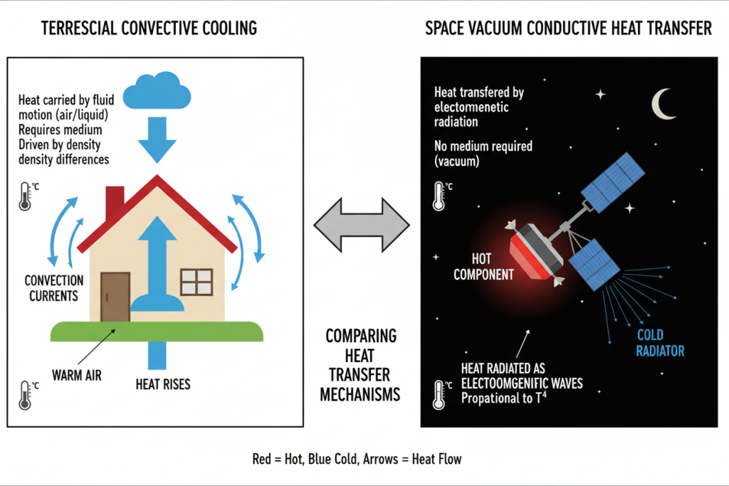
In terrestrial electronics, thermal management often relies on fans, heat sinks, and ambient air circulation. In the vacuum of space, these conventional methods are entirely useless. A satellite orbiting Earth experiences brutal temperature fluctuations, typically plunging to -150°C in the Earth’s shadow and soaring to +150°C when exposed to direct solar radiation.
For the hardware inside, particularly high-frequency RF modules and processing units, the heat generated by active components has nowhere to go. If this thermal energy is not efficiently extracted, the resulting thermal stress will degrade signal integrity, accelerate material fatigue, and ultimately destroy the circuit board.
Therefore, aerospace thermal management must rely 100% on thermal conduction. Every joule of heat must be physically guided through the internal structure of the PCB—using specialized copper structures and advanced materials—until it reaches the satellite’s external thermal radiators. Designing high-reliability rigid-flex PCB manufacturing processes requires a fundamental shift in how engineers view board stackups, treating the PCB not just as an electrical circuit, but as a primary thermal pipeline.
Core Concepts Simplified
To engineer a zero-failure board for space, we must first translate complex thermodynamic and material science challenges into actionable design principles.
Conduction-Only Heat Transfer (The “Highway” Analogy)
Imagine a bustling city (your high-power processor) trying to evacuate vehicles (heat) during rush hour. On Earth, you have helicopters and airplanes (air convection) to help clear the traffic. In space, the airspace is closed. You must rely entirely on ground highways. Thermal vias and heavy copper pours act as these dedicated, high-speed multi-lane highways. They physically channel the heat away from the processor, through the dense layers of the PCB, routing it directly to the spacecraft’s cold plates.
CTE Mismatch (The “Bending Wire” Analogy)
Coefficient of Thermal Expansion (CTE) measures how much a material expands when heated and contracts when cooled. A rigid-flex PCB is a hybrid of different materials (stiff FR-4/polyimide cores and flexible polyimide films). When exposed to a 300°C temperature swing, these materials expand and shrink at different rates.
Think of bending a frozen metal wire back and forth. Eventually, the stress causes it to snap. If the rigid section expands faster than the flexible section, the rigid-flex transition zone experiences immense shear stress. This microscopic tug-of-war will literally tear apart plated through-holes (PTH) and microvias, severing the electrical connection.
Material Outgassing (TML & CVCM)
In a high-vacuum environment, standard plastics, adhesives, and epoxies vaporize, releasing volatile organic compounds. This is known as outgassing. If these gases condense on the satellite’s sensitive optical lenses, star trackers, or solar panels, they cause permanent mission failure. Space-grade PCBs must strictly adhere to NASA outgassing standards, focusing on Total Mass Loss (TML) and Collected Volatile Condensable Material (CVCM).
Comparison: Earth-Bound vs. Space-Bound Thermal Management
| Feature / Metric | Terrestrial Commercial PCB | Aerospace / Satellite Rigid-Flex PCB |
|---|---|---|
| Primary Cooling Method | Convection (Fans, Airflow) & Conduction | 100% Conduction (Thermal Vias, Cold Plates) |
| Operating Temperature | 0°C to +85°C | -150°C to +150°C (Extreme Cycling) |
| Material Outgassing Limits | Rarely specified | TML < 1.0%, CVCM < 0.1% (NASA Standards) |
| Transition Zone Stress | Minimal (Stable environment) | Extreme (High risk of via fracture due to CTE) |
| Manufacturing Standard | IPC-6012 Class 2 | IPC-6013 Class 3 / 3A (Space Addendum) |
Step-by-Step Guide: Designing for Zero-Failure in Space
Achieving mission-critical reliability requires a meticulous approach to board stackup, material selection, and routing. Here is the definitive engineering workflow for thermal management in satellite rigid-flex PCBs.
Establishing the Conduction-Only Thermal Pipeline
Since convection is out of the equation, your copper design is your only thermal defense.
- Deploy Heavy Copper Planes: Utilize 2 oz to 4 oz heavy copper for internal ground and power planes. These act as massive heat spreaders, pulling localized heat away from high-power RF amplifiers and FPGAs.
- Optimize Thermal Via Arrays: Place dense arrays of thermal vias directly beneath heat-generating components.
- Engineering Rule: Vias should be filled with conductive epoxy (e.g., silver-filled) and capped/plated over (VIPPO – Via-in-Pad Plated Over). Unfilled vias trap air, which provides zero thermal benefit in a vacuum.
- Direct Chassis Coupling: Design thermal edge rails. Extend the internal copper planes to the edges of the rigid sections so they can be physically clamped to the satellite’s aluminum or beryllium thermal chassis.
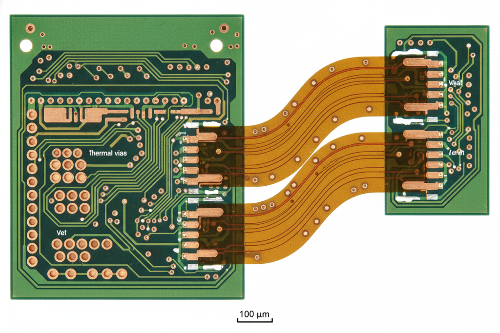
Mitigating CTE Mismatch at Rigid-Flex Transition Zones
The transition zone—where the flexible polyimide enters the rigid board—is the #1 point of failure during extreme thermal cycling.
- Material Matching: Never mix high-CTE epoxies with low-CTE polyimides. Use low-CTE, high-Tg (Glass Transition Temperature) polyimide materials for both the rigid and flexible sections to ensure they expand in unison.
- Staggered Vias: Avoid placing microvias directly adjacent to the transition line. The mechanical stress is highest here. Offset critical vias at least 2.54mm (100 mils) away from the rigid-flex interface.
- Teardrop Pads: Apply teardrop shapes to all trace-to-pad connections in the transition zone to add mechanical strength against thermal expansion shearing forces.
Engineering Specs/Data Table: Material Selection for Vacuum Environments
| Material Property | Standard FR-4 (Not recommended) | Space-Grade Polyimide (APICAL/Kapton) | Target Space Requirement |
|---|---|---|---|
| Tg (Glass Transition Temp) | 130°C – 170°C | > 250°C | Must exceed max operating temp (+150°C) |
| Z-Axis CTE (Below Tg) | 50 – 60 ppm/°C | 35 – 45 ppm/°C | As low as possible to prevent via cracking |
| TML (Total Mass Loss) | > 1.5% | < 0.8% | < 1.0% (NASA SP-R-0022A) |
| CVCM (Condensable Material) | > 0.2% | < 0.05% | < 0.1% (NASA SP-R-0022A) |
Synergy Between Thermal Design and Signal Integrity
Thermal management does not exist in a vacuum (pun intended). In satellite communication systems, excessive heat directly degrades signal integrity. As the temperature of copper traces rises, their electrical resistance increases, leading to voltage drops and the generation of thermal noise (Johnson-Nyquist noise).
By efficiently evacuating heat through solid conduction pathways, you simultaneously stabilize the electrical characteristics of the board. This thermal stability is the foundational layer for advanced anti-interference design specifications required in military and aerospace communication equipment. Furthermore, the heavy copper ground planes used for heat spreading double as excellent electromagnetic shields, providing robust EMC solutions that protect sensitive RF signals from cosmic radiation and internal crosstalk.
Expert Tips & Common Pitfalls to Avoid
When browsing engineering forums like r/AerospaceEngineering or EEVblog, you will frequently encounter horror stories of satellite sub-systems failing during thermal vacuum (TVAC) testing. Here are the hard-learned lessons from the field:
- Pitfall 1: Ignoring Aspect Ratios in Microvias.
- The Mistake: Designing microvias with an aspect ratio greater than 0.8:1 in the rigid-flex transition zone.
- The Result: During the -150°C cooling phase, the rapid contraction causes the copper plating inside the via to barrel and crack (barrel fatigue), leading to intermittent open circuits.
- The Fix: Keep microvia aspect ratios strictly under 0.8:1, and enforce a minimum copper plating thickness of 25µm (1 mil) in the via walls.
- Pitfall 2: Using Standard Acrylic Adhesives.
- The Mistake: Using standard acrylic-based coverlay adhesives in the flexible section.
- The Result: Acrylic adhesives have massive Z-axis expansion rates and severe outgassing properties. In a vacuum, they will outgas and coat the satellite’s optics, while simultaneously tearing the board apart from the inside during thermal cycling.
- The Fix: Exclusively use adhesiveless copper-clad laminates (FCCL) and polyimide-based adhesives.
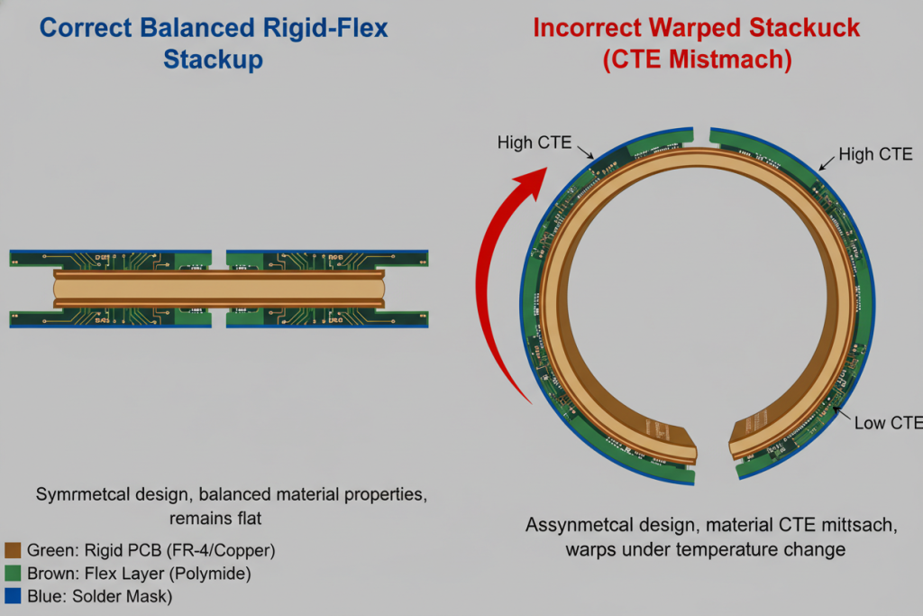
- Pitfall 3: “Just add more copper” without balancing.
- The Mistake: Flooding one side of the transition zone with heavy copper for thermal mass, while leaving the other side sparse.
- The Result: The uneven CTE causes the board to warp and bow dramatically during temperature shifts, ripping the flexible polyimide away from the rigid core (delamination).
- The Fix: Always maintain a symmetrical stackup. Copper distribution must be balanced on both sides of the neutral axis.
Conclusion & Final Thoughts
Designing rigid-flex PCBs for satellite communications requires engineers to fight a multi-front war against vacuum environments, extreme thermal cycling, and stringent outgassing limitations. Success lies in abandoning terrestrial cooling concepts and fully embracing conduction-only architectures, low-CTE space-grade polyimides, and rigorous transition zone reinforcement.
Quick Summary: Satellite Rigid-Flex Thermal Strategy
| Design Phase | Critical Action Item | Primary Benefit |
|---|---|---|
| Material Selection | Mandate Adhesiveless Polyimide (TML <1%, CVCM <0.1%) | Prevents optical contamination & withstands 300°C temp swings |
| Thermal Routing | Utilize VIPPO thermal vias & 2oz+ heavy copper planes | Maximizes pure thermal conduction to spacecraft chassis |
| Transition Zone | Enforce via keep-out zones & balanced copper symmetry | Eliminates via micro-fractures caused by CTE mismatch |
| Signal Integrity | Integrate thermal planes as EMC shielding | Reduces thermal noise & enhances anti-interference |
By adhering strictly to IPC-6013 Class 3/A standards and NASA outgassing protocols, you ensure that your hardware will survive the violent launch phase and operate flawlessly in the silent, extreme vacuum of space for decades.