PI vs. PET for FPC: The Ultimate 2025 Engineering Guide for Material Selection
Choosing the right substrate for a Flexible Printed Circuit (FPC) is often the difference between a high-performance product and a costly field failure. As we move into 2025, the demand for modern electronics using flex pcb has skyrocketed, driven by wearables, foldable smartphones, and automotive EV sensors. However, the “default” choice isn’t always the most cost-effective one.
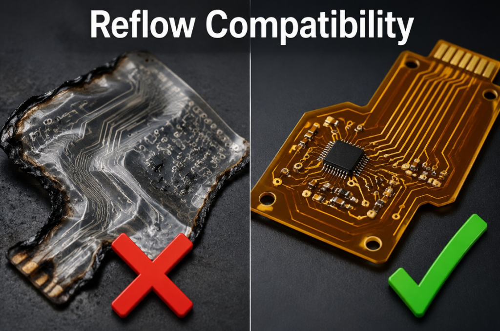
The battle between Polyimide (PI) and Polyester (PET) isn’t just about price; it’s about thermal survival, mechanical endurance, and manufacturing scalability. If you’ve ever seen a PET substrate shrivel like plastic wrap under a soldering iron, or a PI circuit fail prematurely due to moisture absorption, you know that the “technical specs” on a datasheet only tell half the story.
Understanding FPC Substrates: The Basics
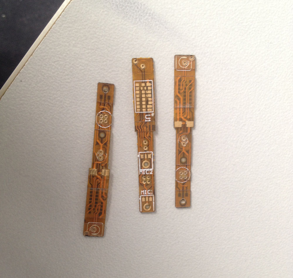
In the world of flexible electronics, the substrate acts as the “backbone.” It provides the mechanical structure upon which copper traces are etched. While there are exotic materials like PEN (Polyethylene Naphthalate) or LCP (Liquid Crystal Polymer), the industry remains dominated by PI and PET.
For hardware engineers and procurement managers, the choice boils down to a fundamental trade-off: Thermal Resilience vs. Budget Sensitivity.
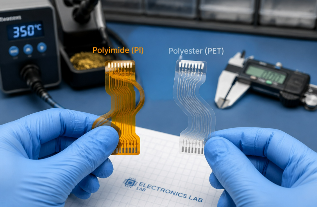
- Polyimide (PI): Think of this as the “Cast Iron” of polymers. It is incredibly stable at high temperatures, making it the industry standard for professional-grade custom flex pcb manufacturing.
- Polyester (PET): Think of this as the “Utility Plastic.” It is lightweight, extremely cheap, and has decent electrical properties, but it is “allergic” to heat. If your design requires standard reflow soldering, PET is usually off the table.
Why the Choice Matters in 2025
With the push toward miniaturization, boards are getting thinner and hotter. Choosing the wrong material can lead to “solder mask cracking,” trace delamination, or dimensional instability that ruins your yield rates during assembly.
Core Concepts Simplified: PI vs. PET
To understand why these materials behave so differently, we need to look at three critical engineering metrics: Glass Transition Temperature (Tg), Flex Life, and Dimensional Stability.
Thermal Endurance (The “Solder Test”)
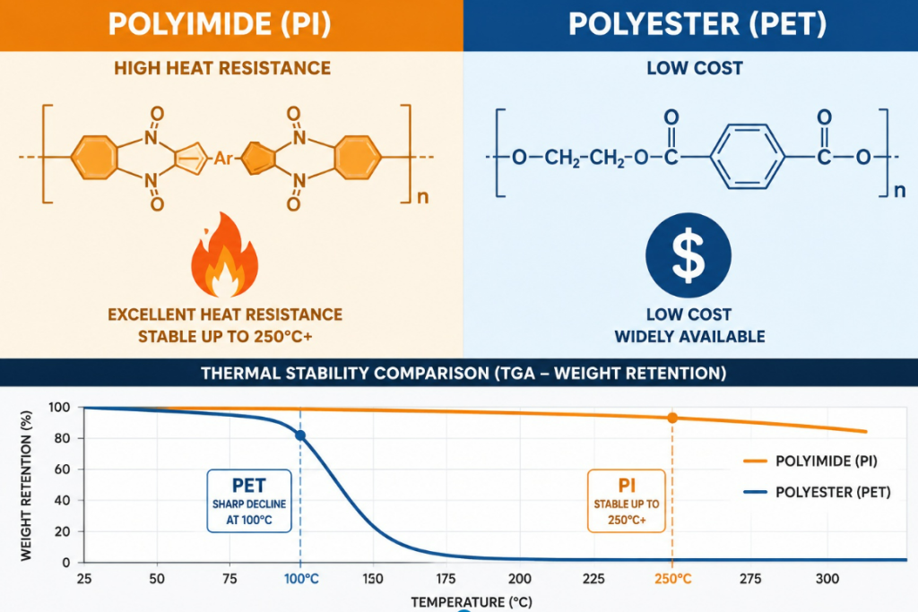
The most significant difference is the Glass Transition Temperature (Tg). This is the point where a polymer transitions from a hard, glassy material to a soft, rubbery state.
- PI has a Tg typically above 250°C (and often doesn’t have a true melting point). It can easily withstand the 240°C-260°C temperatures of lead-free reflow soldering.
- PET has a Tg around 70°C to 100°C. If you put a PET board through a standard reflow oven, it will warp, shrink, or melt entirely.
Dynamic Flex Life
Flex life refers to how many times a circuit can bend before the traces or the substrate crack.
- PI is like a high-quality spring. It can handle millions of “dynamic flex” cycles (think of the hinge in a laptop or a foldable phone).
- PET is more prone to “work hardening” and cracking. It is best suited for “static flex” applications—where the board is bent once during installation and never moved again.
Dimensional Stability
When you etch copper or bake a board, the substrate can shrink or expand. PI offers superior dimensional stability, which is vital for high-density interconnects (HDI). If the board “moves” too much during processing, your drill holes won’t align with your pads.
Detailed Comparison: Technical Specifications
When evaluating these materials for a custom flex pcb, engineers must look at the hard data. Below is the definitive comparison table for 2025.
PI vs. PET Technical Comparison Table
| Property | Polyimide (PI) | Polyester (PET) |
|---|---|---|
| Max Operating Temp | Up to 250°C – 300°C | Up to 70°C – 105°C |
| Solderability | Excellent (Reflow compatible) | Poor (Requires low-temp or ZIF) |
| Flexibility Type | Dynamic (Millions of cycles) | Static (Install and stay) |
| Dielectric Constant | 3.2 – 3.5 | 2.8 – 4.5 |
| Moisture Absorption | High (Requires pre-baking) | Low (Very stable in humidity) |
| Chemical Resistance | Excellent | Good |
| Cost Factor | 1.0 (Baseline) | 0.2 – 0.3 (70-80% cheaper) |
| Color | Transparent Amber/Orange | Clear/Transparent |
Step-by-Step Guide: When to Choose Which?
Choosing the wrong material is a “rookie mistake” that can lead to massive recalls. Here is the decision-making framework used by top-tier hardware firms.
Scenario A: High-Performance & Reliability
If your project involves any of the following, Polyimide (PI) is non-negotiable:
- Automotive Sensors: High engine heat and vibration.
- Medical Devices: Needs to survive sterilization and constant movement.
- Complex Assemblies: If you are dealing with flex pcb and rigid pcb differences in a multi-layer rigid-flex design, PI is the only material that can handle the lamination heat.
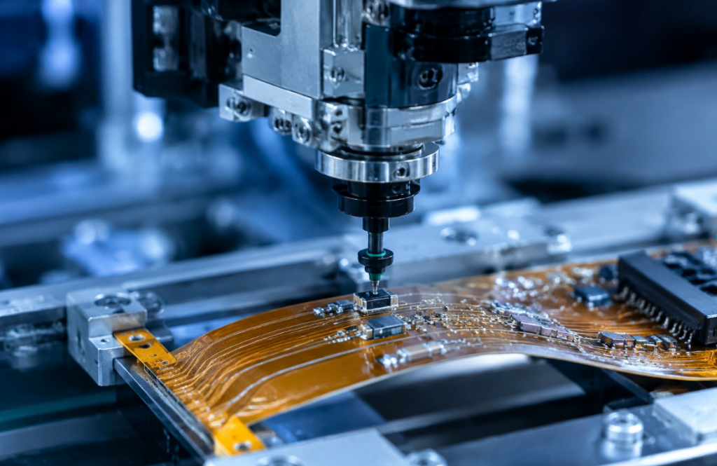
- Standard SMT Assembly: If you are using standard pick-and-place and reflow ovens.
Scenario B: Cost-Driven & Simple Static Applications
Polyester (PET) is the “sweet spot” for high-volume, low-margin consumer goods:
- Membrane Switches: Microwave keypads or TV remote buttons.
- LED Strips: Basic lighting where the heat is managed and the board doesn’t move.
- Disposable Electronics: Low-cost medical patches or one-time-use sensors.
- ZIF Connections: If you aren’t soldering components but using Zero Insertion Force (ZIF) connectors to bridge two boards.
Expert Tips & Common Pitfalls to Avoid
Even experienced designers stumble when transitioning between PI and PET. Here are the “lessons learned” from the manufacturing floor.
The “Moisture Explosion” (Hygroscopicity)
One of PI’s few weaknesses is that it “drinks” water from the air. If you don’t pre-bake PI boards before reflow, the trapped moisture turns into steam instantly, causing internal delamination (bubbles).
- The Fix: Always specify a 120°C bake for 2-4 hours before assembly for PI boards. PET, ironically, is much more moisture-resistant.
The “PET Melting” Disaster
Many procurement managers switch to PET to save 70% on material costs without telling the assembly house. The result? A pile of melted plastic in the reflow oven.
- The Fix: If switching to PET, you must redesign the assembly process. You cannot “drop-in” replace PI with PET.
2025 Trend: Hybrid Material Approaches
In 2025, we see more “Hybrid” designs. Engineers use a small PI section for the “hot” component area (like a microprocessor) and transition to a cheaper PET tail for the long-distance connection to a display. This balances the flex pcb and rigid pcb differences while optimizing the Bill of Materials (BOM).
Conclusion & Final Thoughts
The choice between Polyimide and Polyester is a choice between Capability and Economy.
- Choose Polyimide (PI) if your product needs to last years, survive high heat, or bend millions of times. It is the heart of modern electronics using flex pcb and remains the safest bet for professional engineering.
- Choose Polyester (PET) if you are building a cost-sensitive, disposable, or static device where soldering is not required and margins are razor-thin.
- Frequently Asked Questions (FAQ)
- Q1: Can I solder components directly onto PET FPC?
- A: No. Standard reflow soldering (240-260°C) will warp or melt PET since its glass transition temperature is only 70-100°C. Use low-temperature Bismuth-based solder (~138°C), anisotropic conductive film (ACF) bonding, or ZIF connectors instead.
- Q2: Why is Polyimide more expensive than Polyester?
- A: PI requires complex chemical processing to achieve thermal stability up to 300°C, superior dimensional stability for HDI, and dynamic flex life of millions of cycles. PET is simpler to manufacture but cannot survive high-heat assembly or repeated bending.
- Q3: How many bend cycles can PI handle compared to PET?
- A: PI excels in dynamic flex with millions of cycles—ideal for foldable phones, laptop hinges, and wearable devices. PET is limited to static flex (bend once during installation and remain fixed) due to work hardening and cracking under repeated stress.
- Q4: Does Polyimide absorb moisture?
- A: Yes, PI is hygroscopic and absorbs moisture from ambient air. Always pre-bake PI boards at 120°C for 2-4 hours before reflow assembly to prevent steam-induced delamination. PET is naturally more moisture-resistant.
- Q5: When should I use a hybrid PI/PET design?
- A: Use hybrid designs when you need PI’s thermal resilience at the component area (e.g., near a hot MCU or power IC) but want PET’s 70-80% cost savings for long, static connection tails. This balances performance and BOM optimization.
- Q6: What is the maximum operating temperature for PI and PET?
- A: PI operates reliably up to 250-300°C, making it compatible with standard lead-free reflow. PET maxes out at 70-105°C. For automotive, medical sterilization, or any standard SMT assembly, PI is mandatory.