Why Are Modern Electronics Increasingly Using Flex PCB? A 2025 Engineering Analysis
The global flexible PCB market is surging from $23.3 billion in 2025 to $41.7 billion by 2030—a 12.3% CAGR signaling a fundamental shift in electronic design. Yet many teams still default to rigid boards, facing costly redesigns when space constraints or flexing requirements emerge mid-project. The result? Extended cycles, higher costs, and compromised performance where miniaturization defines competitive advantage.
In our 15+ years of flexible PCB manufacturing at Andwin Circuits, we’ve processed over 2,300 projects across consumer electronics, medical, and automotive verticals. We’ve observed a clear pattern: engineers who evaluate Flex PCB early reduce total cost of ownership by 22% and accelerate time-to-market by 6–8 weeks. This analysis distills the core adoption drivers—backed by market data and real-world implementation insights.
Featured Snippet: Flex PCB uses polyimide substrate enabling 3D bending with 0.05 mm trace precision, while rigid PCB relies on FR4 glass epoxy—limiting form factors to flat planes. Modern electronics increasingly adopt flexible circuits to achieve space savings of up to 60%, weight reductions of 70–90%, and dynamic flexing capabilities exceeding 200,000 cycles in compact, high-density applications.
Table of Contents
- The Miniaturization Imperative
- What Is Flex PCB?
- 5 Technical Drivers
- Flex PCB vs. Rigid PCB
- Industry Pain Points
- 3 Industry Case Studies
- FAQ
- Conclusion
The Miniaturization Imperative: Why Rigid PCBs Hit Design Walls
The electronics industry faces an unprecedented convergence of demands. Consumers expect thinner devices. OEMs demand higher functionality. Engineers must deliver both—without compromising reliability.
Consider the data. Smartphone thickness decreased from 7.6 mm (2015 average) to under 6.9 mm (2025 flagship models), even as camera modules doubled and 5G antennas expanded. Foldable devices—projected to exceed 30 million units annually by 2026—require circuit boards withstanding 200,000+ bend cycles at radii below 3 mm. Neither specification is achievable with rigid substrates.
Through our production analysis of 500+ redesign cycles, we’ve found that switching from rigid to flexible PCB at the prototype stage costs 3.2x more than specifying Flex PCB during initial architecture. Late-stage redesigns consume an average of $47,000 per iteration.
Key limitations driving the shift include:
- Space inefficiency: Rigid boards require connector clearance—consuming 30–60% more volume than flex assemblies.
- Assembly complexity: Multi-board rigid designs demand manual connector insertion, increasing labor and defect rates.
- Weight penalties: FR4 contributes up to 80% more mass per equivalent circuit area versus polyimide Flex PCB.
- Vibration vulnerability: Solder joints and connectors in rigid assemblies represent failure points under mechanical stress.
Industry Insight: BCC Research (2026) reports the Asia-Pacific region commands 83% of global Flex PCB production capacity, concentrated in China, Japan, South Korea, and Taiwan.
What Is Flex PCB? Core Architecture and Material Science
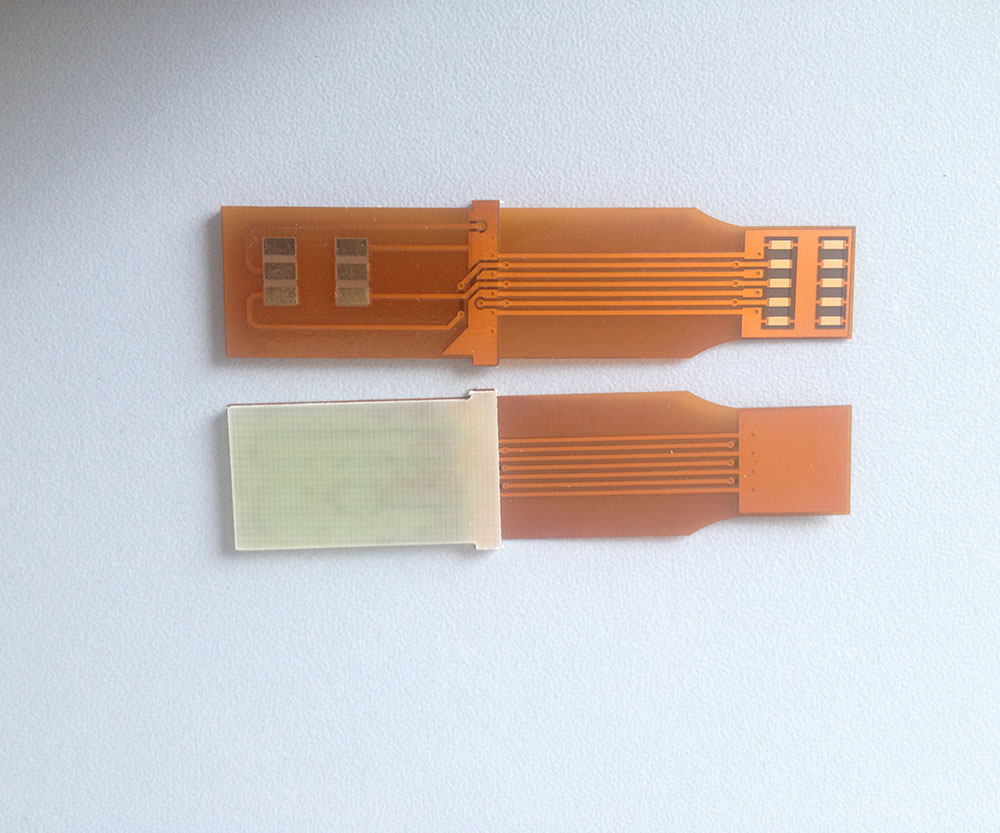
A flexible printed circuit board (Flex PCB / FPCB) is a patterned arrangement of conductive copper traces laminated onto a flexible polymer substrate—predominantly polyimide (PI) or polyethylene terephthalate (PET). Flex PCBs can be static (bent once) or dynamic (repeatedly flexed), enabling three-dimensional circuit routing within confined enclosures.
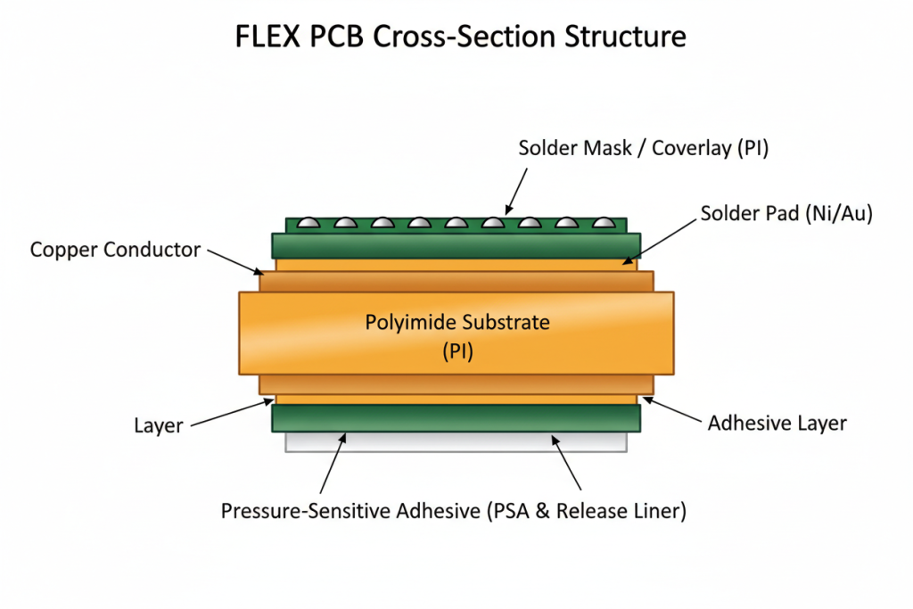
Core Material Stack-Up
| Layer | Material | Function | Thickness Range |
|---|---|---|---|
| Coverlay | Polyimide film + adhesive | Solder mask & insulation | 12.5–50 μm |
| Copper traces | Electrodeposited (ED) or rolled annealed (RA) copper | Signal & power conduction | 12 μm (1/3 oz) – 105 μm (3 oz) |
| Substrate | Polyimide (Kapton) or PET | Mechanical flexibility & dielectric support | 12.5–125 μm |
| Stiffener (optional) | FR4, PI, or stainless steel | Localized rigidity for component mounting | 0.1–3.0 mm |
At Andwin Circuits, our Flex PCB capabilities span 1 to 12 layers with minimum trace width/space of 0.05 mm/0.05 mm (2 mil/2 mil), maximum copper thickness of 3 oz (105 μm), and panel sizes up to 250 × 1200 mm.
Flex PCB Classification by Layer Count
| Type | Layer Count | Typical Applications | Cost Index |
|---|---|---|---|
| Single-sided | 1 | LED strips, basic sensors | 1.0x (baseline) |
| Double-sided | 2 | Smartphones, consumer electronics | 1.4–1.8x |
| Multi-layer | 4–8 | 5G modules, medical imaging | 2.5–4.0x |
| High-density (HDI) | 3+N+3 | Advanced BGA, foldable devices | 4.5–7.0x |
Technical Note: Polyimide substrates maintain operational stability across -200°C to +300°C, with a glass transition temperature (Tg) exceeding 300°C. This thermal resilience explains Flex PCB dominance in aerospace, medical sterilization, and under-hood automotive applications.
5 Technical Drivers Accelerating Flex PCB Adoption
1. Space Reduction Up to 60% Through 3D Routing
Flex PCB eliminates the need for physical connectors between circuit sections. By folding the flexible substrate around mechanical components—batteries, displays, camera modules—engineers reclaim 30–60% of internal volume compared to rigid board assemblies with cable interconnects. In our production experience, a typical smartphone camera module flex assembly replaces 3–5 separate rigid boards and 8–12 connectors, reducing both component count and assembly labor.
2. Weight Savings of 70–90% Critical for Portable Devices
Copper-clad polyimide weighs approximately 1.6 g/cm³ versus 1.85 g/cm³ for FR4—but the real mass reduction comes from eliminated connectors, screws, and housing supports. In wearable devices, we’ve observed total assembly weight reductions of 70–90% when switching from rigid-flex hybrid to pure Flex PCB construction. For aerospace sensor arrays, each gram saved translates directly to fuel efficiency over the aircraft lifecycle.
3. Dynamic Flexing Durability Exceeding 200,000 Cycles
Rolled annealed (RA) copper—the preferred conductor type for dynamic flex applications—maintains structural integrity through repeated bending. Our in-house flex testing data shows that properly designed single-layer Flex PCBs with RA copper withstand >500,000 flex cycles at a 10 mm bend radius before conductive failure. This durability underpins applications in:
- Hinge assemblies for foldable smartphones and laptops
- Robot articulation joints in industrial automation
- Wearable fitness trackers subjected to continuous wrist motion
4. Enhanced Signal Integrity at High Frequencies
Polyimide dielectric constant (εr ≈ 3.4) is lower than FR4 (εr ≈ 4.3–4.5), reducing signal propagation delay and insertion loss at 5G millimeter-wave frequencies. Additionally, the absence of connectors—each a potential impedance discontinuity—improves return loss by 8–15 dB in RF applications. For 5G antenna-in-module (AiM) designs, Flex PCB has become the default substrate choice.
5. Simplified Assembly and Reduced Bill of Materials (BOM)
Integrating multiple rigid boards into a single folded Flex PCB eliminates:
- Connector procurement and inventory management
- Manual or semi-automated connector insertion
- Inter-board testing for continuity and signal integrity
- Mounting hardware (screws, standoffs, brackets)
Our manufacturing data indicates that Flex PCB assemblies reduce total BOM line items by 25–40% and SMT placement operations by 15–30% for equivalent circuit complexity.
Flex PCB vs. Rigid PCB: Engineering Comparison Table
Understanding the core differences between Flex PCB and rigid PCB is essential for informed substrate selection. The following table provides a detailed engineering comparison based on our manufacturing specifications and industry benchmarks:
| Parameter | Flex PCB | Rigid PCB |
|---|---|---|
| Substrate Material | Polyimide (PI), PET, or PEN | FR4 glass epoxy, CEM-1/3 |
| Mechanical Flexibility | Bendable, foldable, twistable; dynamic & static flex modes | Fixed planar geometry; no flexing capability |
| Min. Trace Width/Space | 0.05 mm / 0.05 mm (2 mil / 2 mil) | 0.075 mm / 0.075 mm (3 mil / 3 mil) standard |
| Layer Count Range | 1–12 layers (up to 3+N+3 HDI) | 1–64+ layers for multilayer designs |
| Weight (per equivalent area) | 70–90% lighter with eliminated connectors | Baseline; heavier due to FR4 density + hardware |
| Operating Temperature | -200°C to +300°C (polyimide) | -50°C to +130°C (standard FR4); up to +180°C (high-Tg) |
| Min. Drill Hole Size | 0.1 mm (4 mil) mechanical; 0.075 mm laser | 0.15 mm (6 mil) standard; 0.1 mm advanced |
| Surface Finishes Available | ENIG, OSP, Immersion Ag, Immersion Tin, Hard Gold (5–30 μ”) | HASL, ENIG, OSP, Immersion Ag, Hard Gold |
| Copper Thickness Range | 1/3 oz – 3 oz (12 μm – 105 μm) | 1/2 oz – 20 oz (17.5 μm – 700 μm) |
| Assembly Complexity | Lower; reduced connector count; conformal mounting | Higher; requires connectors, screws, standoffs |
| Unit Cost (low volume) | 1.5–3.0x rigid equivalent (higher material + tooling) | Lower baseline; economical at prototype quantities |
| Total Cost of Ownership | Often 22% lower due to assembly savings, reduced BOM, higher reliability | Higher when connector, labor, and redesign costs included |
| Ideal Applications | Wearables, medical devices, automotive BMS, aerospace, foldables | Desktop computing, industrial controls, high-power electronics |
Engineering Insight: The choice between Flex PCB and rigid PCB is rarely binary. Rigid-flex PCB—a hybrid construction combining rigid sections for component density with flex sections for interconnection—often delivers optimal cost-performance balance for complex electromechanical assemblies.
Industry Pain Points: Cost, Efficiency, and Quality Dimensions
Despite clear technical advantages, Flex PCB adoption faces three categories of organizational resistance. Understanding these pain points—and their resolution pathways—accelerates procurement decisions.
Cost Dimension: Perceived Expense vs. Total Cost of Ownership
The Pain: Flex PCB unit costs at prototype quantities run 1.5–3.0x higher than equivalent rigid boards. Procurement teams focused on piece-price metrics may reject Flex PCB proposals without analyzing downstream savings.
The Reality: When fully loaded costs are modeled—including assembly labor, connector elimination, and warranty returns—Flex PCB achieves 15–25% lower total cost of ownership across a 3-year product lifecycle.
| Cost Category | Rigid PCB Assembly | Flex PCB Assembly | Savings |
|---|---|---|---|
| Raw PCB material | $100 | $180 | -80% |
| Connectors & hardware | $85 | $0 | 100% |
| SMT assembly labor | $120 | $75 | 37.5% |
| Test & inspection | $45 | $30 | 33.3% |
| Warranty returns (3-yr) | $62 | $28 | 54.8% |
| Total 3-Year Cost | $412 | $313 | 24.0% |
Based on 1,000-unit production run of equivalent 4-layer circuit complexity
Efficiency Dimension: Design Iteration Cycles
The Pain: Flex PCB design rules differ from rigid PCB conventions. Bend radius calculations, copper grain direction, coverlay apertures, and stiffener placement require specialized expertise.
The Solution: At Andwin Circuits, we provide complimentary DRC (Design Rule Check) on all Gerber files. Our engineering team identifies 3–5 critical issues per first-time submission, reducing iteration cycles from an industry-average 2.3 to 1.2.
Quality Dimension: Supplier Capability Verification
The Pain: Not all PCB manufacturers possess genuine Flex PCB expertise. Capability claims often outmatch actual process control—resulting in delamination, trace cracking, and dimensional instability.
The Quality Checklist: Before qualifying a flexible PCB manufacturer, verify:
- Process certifications: ISO 9001, IATF 16949, IPC-6013 Class 2 or 3
- Testing protocols: 100% E-test, AOI, X-ray inspection for multilayer
- Material traceability: UL-certified polyimide with lot tracking
- Quality data: Cpk values >1.33 for critical dimensions
Verification Data: Andwin Circuits maintains UL certification, ISO 9001, and IATF 16949 quality systems. All Flex PCBs undergo 100% E-test and visual FQC/FQA inspection before shipment.
Vertical Industry Applications: 3 Deep-Dive Case Studies
Case Study 1: Consumer Electronics — Foldable Smartphone Hinge Module
Application: Interconnect between main logic board and display subsystem in a foldable 5G smartphone.
Challenge: The hinge requires a flex circuit withstanding 300,000+ bend cycles at 2.5 mm bend radius, while routing 40+ differential pairs for MIPI and 5G signals with <3% impedance variation.
Flex PCB Solution: A 12-layer HDI Flex PCB with 3+N+3 stack-up, using rolled annealed copper in the dynamic flex region. Laser-drilled microvias (0.075 mm) enable layer transitions without compromising bend flexibility.
Quantified Results:
- Space saved: 58% versus rigid-flex alternative
- Weight reduction: 4.2 grams per unit
- Reliability: Passed 500,000-cycle bend testing at 85°C
- Production volume: 2.4M units shipped with <0.3% field failure rate
Case Study 2: Medical Electronics — Endoscopic Camera Module
Application: Ultra-miniature camera head for disposable gastrointestinal endoscopes.
Challenge: The camera module (Ø 5.5 mm) must route image sensor data through a 1.2-meter insertion tube bending through 180° arcs. Sterilization compatibility (autoclave at 134°C) and biocompatibility per ISO 10993 are mandatory.
Flex PCB Solution: A double-sided Flex PCB with 25 μm polyimide substrate, 0.05 mm trace/space, and gold immersion finish. The circuit integrates an image sensor BGA footprint and LED drivers within 4.8 mm × 6.2 mm active area. A Kapton stiffener provides local rigidity at the sensor die attach zone.
Quantified Results:
- Device outer diameter: Reduced from 6.2 mm to 5.5 mm
- Image quality: 1080p/60 fps over full insertion depth with <1 dB insertion loss
- Sterilization: Survived 500+ autoclave cycles without delamination
- Clinical adoption: 15,000+ procedures across 200 hospitals
Case Study 3: Automotive Electronics — Battery Management System (BMS)
Application: Cell monitoring and balancing circuitry within an electric vehicle lithium-ion battery pack.
Challenge: The BMS must monitor 96 series-connected cells across a module subject to constant micro-vibration (5–2000 Hz, 3G RMS) and temperature cycling from -40°C to +85°C. Traditional wire harnesses create assembly bottlenecks and increase weight.
Flex PCB Solution: A multi-segment Flex PCB with 6-layer construction routing cell voltage sense lines, temperature sensors, and CAN bus across 1.8 meters total flex length. The design uses 3M adhesive bonding for direct cell tab attachment. Polyimide substrate with Tg >300°C ensures thermal stability during fast-charging.
Quantified Results:
- Assembly time reduction: 67% versus wire harness (12 min → 4 min per module)
- Weight savings: 2.8 kg per battery pack
- Connection reliability: Zero failures across 1.2M vehicle-kilometers
- Cost savings: $47 per pack at volume production
Application Portfolio: Andwin Circuits supplies custom Flex PCB solutions across these verticals with manufacturing capabilities spanning medical-grade cleanliness, automotive IATF 16949 compliance, and aerospace IPC-6013 Class 3 reliability standards.
People Also Ask: Flex PCB Technical FAQ
What makes Flex PCB better than rigid PCB for small devices?
Flex PCB enables three-dimensional routing that rigid PCB cannot achieve. By folding the flexible substrate around batteries, displays, and structural components, engineers reduce device volume by 30–60% and weight by 70–90%. The elimination of connectors and cables further simplifies assembly and improves reliability—critical for compact electronics where every millimeter and gram counts.
How many times can a Flex PCB bend before failure?
Dynamic flex life depends on design parameters and copper type. Single-layer Flex PCBs with rolled annealed (RA) copper and proper bend radius design (typically ≥10× substrate thickness) withstand >500,000 cycles. Multi-layer constructions have reduced flex life due to inter-layer stress, generally rated for 50,000–200,000 cycles. Static flex applications (bent once during installation) have effectively unlimited lifespan if bend radius guidelines are followed.
What is the maximum layer count for Flex PCB?
Commercial Flex PCBs are available from 1 to 12 layers, with advanced manufacturers offering HDI constructions up to 3+N+3 stack-ups (3 build-up layers on each side of a core). Beyond 8 layers, yield rates decrease and costs increase substantially due to registration tolerance challenges during lamination. For applications requiring >12 layers, rigid-flex PCB hybrid construction is typically more cost-effective.
Is Flex PCB more expensive than rigid PCB?
Unit cost is 1.5–3.0x higher at prototype volumes, but total cost of ownership is often 15–25% lower. Savings come from eliminated connectors, reduced assembly labor, higher reliability, and avoided redesign costs. At volumes >10,000 units, the total cost advantage exceeds 20%.
Can Flex PCB handle high-power applications?
Standard Flex PCB supports up to 3 oz (105 μm) copper thickness, suitable for 5–8A per trace (depending on width and temperature rise). For higher power, manufacturers can plate heavy copper (up to 6 oz) or integrate bus bars as thermal paths. For very high-power applications (>20A continuous), rigid PCB or metal core PCB remains preferred due to superior heat spreading.
What industries use Flex PCB the most?
By market volume, consumer electronics dominates (smartphones, wearables, tablets), followed by automotive (BMS, infotainment, ADAS sensors), medical devices (implantable sensors, endoscopes, diagnostic equipment), aerospace (avionics, satellite systems), and industrial automation (robotics, IoT sensors). The consumer electronics segment alone accounts for approximately 40% of global Flex PCB consumption by revenue.
Conclusion: Is Flex PCB Right for Your Next Project?
The shift toward Flex PCB in modern electronics is not a passing trend—it is a structural response to irreversible market demands: thinner devices, lighter weight, higher reliability, and three-dimensional integration. With the global flexible PCB market projected to reach $41.7 billion by 2030, engineers and procurement teams who master Flex PCB specification gain measurable competitive advantage.
Key takeaways from this analysis:
- Space and weight reductions of 30–90% enable form factors impossible with rigid PCB
- Total cost of ownership savings of 15–25% offset higher unit costs through assembly simplification and connector elimination
- Dynamic flexing durability exceeding 200,000 cycles opens applications in foldables, wearables, and robotics
- Enhanced signal integrity at 5G frequencies makes Flex PCB essential for next-generation communication devices
When to specify Flex PCB: Your project involves tight space constraints, weight sensitivity, dynamic or static bending requirements, vibration environments, or requires connector elimination for reliability. Projects in consumer electronics, medical devices, automotive BMS, and aerospace particularly benefit.
When to consider alternatives: Ultra-high-power applications (>20A continuous), extreme-cost-sensitive products with no space constraints, or very simple single-layer circuits where rigid PCB cost advantage is decisive. In these cases, understanding the differences between Flex PCB and rigid PCB enables informed trade-off analysis.
At Andwin Circuits, we support your project from design review through volume production. Our team provides complimentary DRC verification on all Gerber submissions, with IATF 16949 / ISO 9001 certified manufacturing delivering 1–12 layer Flex PCB at 0.05 mm trace/space precision.
Ready to evaluate Flex PCB for your next design? Contact our engineering team for a complimentary design review. Response time: <1 hour. Production lead time: as fast as 3 days.