How to Read and Understand Flexible PCB Datasheets: A Practical Guide
Flexible PCB datasheets contain critical specifications that determine whether a flex circuit will survive in your application. But unlike rigid board specs, flex parameters involve material science, mechanical stress, and thermal behavior that many engineers encounter for the first time. This guide walks through the essential datasheet sections with the context you need to make informed decisions.
Table of Contents
- Understanding Substrate Material Specifications
- Mechanical Properties: Bend Radius and Flex Life
- Electrical Characteristics in Flex Circuits
- Thermal Performance Parameters
- Construction Details: Adhesive vs Adhesiveless
- Dimensional Tolerances and Manufacturing Limits
- Reading Between the Lines: What Datasheets Don’t Tell You
- Practical Checklist for Datasheet Review
1. Understanding Substrate Material Specifications
The substrate is the foundation of every flex PCB, and datasheets start here. In our projects involving wearable medical devices, substrate choice has been the difference between 50,000 flex cycles and catastrophic failure at 5,000.
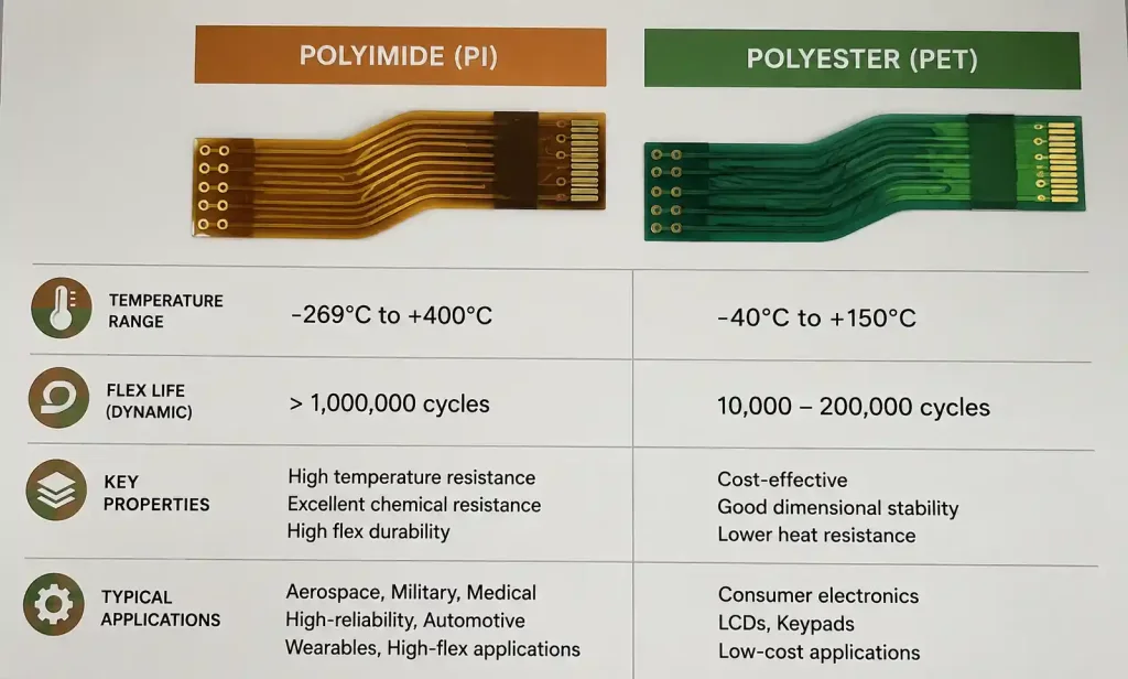
Polyimide (PI) vs Polyester (PET)
Most professional datasheets specify polyimide film, but understanding the trade-offs matters:
| Property | Polyimide (PI) | Polyester (PET) |
|---|---|---|
| Temperature Range | -269°C to +400°C | -70°C to +150°C |
| Flex Life | Excellent (100k+ cycles) | Moderate (10k-50k cycles) |
| Cost | Higher | 40-60% lower |
| Chemical Resistance | Superior | Limited |
| Typical Applications | Medical, aerospace, automotive | Consumer electronics, disposables |
What to look for in datasheets: The grade of polyimide matters. “High-performance PI” typically refers to films with improved dimensional stability and lower moisture absorption. Some manufacturers specify “Kapton®-equivalent” material—this references DuPont’s polyimide standard but may have subtle differences in thermal cycling performance.
Film Thickness Specifications
Datasheets list substrate thickness in micrometers (25µm, 50µm, 75µm, 125µm are common). Thinner isn’t always better:
- 25µm substrates: Maximum flexibility, suitable for dynamic flex applications with tight bend radii (medical catheters, camera modules)
- 50µm substrates: Balance of flexibility and handling strength, most common for general flex applications
- 75-125µm substrates: Used when electrical insulation or mechanical reinforcement is prioritized over extreme flexibility
Real-world consideration: In a recent smartwatch project, we initially specified 25µm for maximum flexibility. During reliability testing, we discovered handling damage during assembly. Switching to 50µm substrate eliminated the issue with negligible impact on the final bend radius.
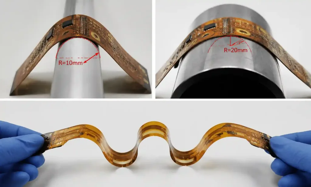
2. Mechanical Properties: Bend Radius and Flex Life
These specifications determine whether your flex circuit survives its mechanical environment—yet they’re often the most misunderstood sections of datasheets.
Minimum Bend Radius
Datasheets specify minimum bend radius as a multiple of total thickness (e.g., “10× thickness” or “6× thickness”). For a 200µm thick flex circuit, 10× means 2mm minimum radius.
Static vs Dynamic Bending:
| Flex Type | Typical Min Radius | Application Example | Datasheet Indicator |
|---|---|---|---|
| Static Flex | 6-10× thickness | Smartphone hinge | “One-time installation bend” |
| Dynamic Flex | 20-50× thickness | Printer carriage cable | “Continuous flexing” specification |
Critical insight: Datasheet minimum radius values assume controlled installation conditions. In our automotive camera module deployments, we discovered that assembly line variations required specifying 1.5× the datasheet minimum radius to maintain acceptable yield.
Flex Life Cycle Data
When datasheets specify “100,000 flex cycles,” ask these questions:
- What bend radius was tested? Larger radii always extend life
- What was the flexing angle? 90° vs 180° makes significant difference
- At what temperature? Cold flexing dramatically reduces cycle life
Example from field experience: A fitness tracker project specified a flex circuit rated for 500,000 cycles at 10mm radius. In actual use, the hinge flexed at 7mm radius (tighter than specified) and users flexed it during winter outdoor runs (-10°C). Field returns showed failures at 80,000 cycles—not a datasheet lie, but a specification mismatch.
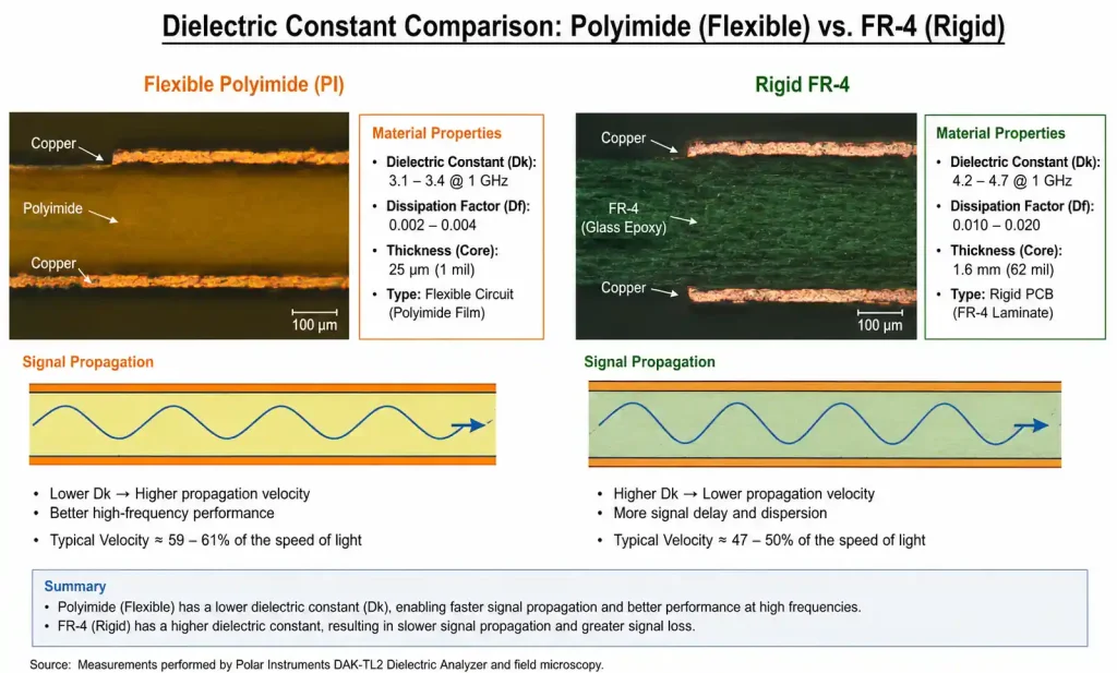
3. Electrical Characteristics in Flex Circuits
Flexible substrates have different electrical properties than rigid FR-4, affecting impedance control and signal integrity.
Dielectric Constant (Dk) and Loss Tangent
Polyimide datasheets typically show:
- Dielectric constant (Dk): 3.1-3.5 at 1MHz (vs FR-4 at 4.2-4.5)
- Loss tangent (Df): 0.002-0.003 at 1MHz
Why this matters: Lower Dk means faster signal propagation and easier impedance matching, but also means you cannot directly reuse rigid PCB impedance calculations for flex sections.
| Parameter | Flex PCB Impact | Design Adjustment |
|---|---|---|
| Lower Dk | Faster signal speed | Narrower traces for same impedance |
| Thinner dielectric | Lower impedance for given geometry | Requires impedance modeling |
| Adhesive layers | Dk variation between adhesive/adhesiveless | Specify adhesiveless for RF >2GHz |
Practical example: In a 5G antenna module, we initially calculated trace impedance using standard calculators. After TDR measurements showed 45Ω instead of target 50Ω, we discovered the datasheet’s Dk was specified at 1MHz but our signals operated at 28GHz, where the actual Dk was 3.3 instead of 3.5.
Copper Thickness and Resistance
Flex datasheets specify copper in ounces (0.5oz, 1oz, 2oz) or micrometers (17µm, 35µm, 70µm):
- 0.5oz (17µm): Standard for dynamic flex, lower stress during bending
- 1oz (35µm): Common for static flex and moderate current
- 2oz (70µm): Power applications, but significantly reduces flexibility
Reading tip: Check if datasheet specifies “rolled annealed copper” (RA) vs “electrodeposited copper” (ED). RA copper has significantly better flex life—critical for dynamic applications but rarely highlighted prominently in datasheets.
4. Thermal Performance Parameters
Thermal specs in flex datasheets differ fundamentally from rigid boards due to limited heat dissipation paths.
Operating Temperature Range
Don’t confuse these three temperature specs:
- Material survival temperature (-269°C to +400°C for PI): Material won’t decompose
- Continuous operating temperature (typically -40°C to +105°C): Rated electrical performance maintained
- Glass transition temperature (Tg): Where mechanical properties change (often not specified for flex)
Critical distinction: A datasheet showing “+400°C” doesn’t mean your circuit can operate continuously at that temperature. This is the material’s short-term solder reflow survival temperature, not operating temperature.
Field lesson: An industrial flex circuit in an engine bay application experienced adhesive delamination at 135°C, well below the polyimide’s 400°C rating. The issue was the acrylic adhesive (rated to 130°C), not the substrate. Always check the thermal limit of every layer in the stack, not just the substrate.
Thermal Conductivity
Flex PCBs have poor thermal conductivity compared to rigid boards:
- Polyimide: 0.12 W/mK
- FR-4: 0.3 W/mK
- Aluminum (for comparison): 200 W/mK
Design implication: Datasheets rarely emphasize this, but flex circuits require aggressive copper area for heat spreading. In a power management flex design, we needed 300% more copper area than an equivalent rigid design to maintain acceptable component temperatures.
5. Construction Details: Adhesive vs Adhesiveless
This datasheet section dramatically affects reliability and performance, especially above 150°C or in RF applications.
Adhesive Construction
Traditional flex uses acrylic adhesive (25-50µm) between copper and substrate:
| Advantage | Disadvantage |
|---|---|
| Lower cost | Temperature limited to 130°C |
| Established process | Thickness variation affects impedance |
| Good availability | Adhesive can outgas or delaminate |
Adhesiveless Construction
Adhesiveless bonds copper directly to polyimide through thermal lamination:
| Advantage | Disadvantage |
|---|---|
| Higher temperature capability (>200°C) | 15-25% cost premium |
| Consistent electrical properties | Limited supplier base |
| Better flex life | Requires specialized tooling |
| No adhesive outgassing | Longer lead times |
Datasheet reading tip: Look for terms like “cast film,” “sputtered copper,” or “2-layer” construction—these indicate adhesiveless. If the datasheet doesn’t explicitly state adhesiveless, assume adhesive construction.
When adhesiveless is non-negotiable: Medical implantables (biocompatibility), automotive under-hood (>150°C), RF above 6GHz (impedance control), aerospace (outgassing restrictions).
6. Dimensional Tolerances and Manufacturing Limits
Flex datasheets often bury critical manufacturing limits in small tables or footnotes—miss these and you’ll design an unfabricated board.
Feature Size Capabilities
| Feature | Standard Flex | Advanced Flex | What to Check in Datasheet |
|---|---|---|---|
| Minimum trace/space | 75/75µm | 50/50µm | “Line width/spacing” section |
| Minimum via diameter | 150µm | 100µm | Often buried in “drilling” notes |
| Pad to outline spacing | 300µm | 200µm | “Edge clearance” or “routing” |
| Coverlay registration | ±75µm | ±50µm | Affects exposed pad soldermask |
Common oversight: Datasheets list capabilities, not recommendations. A manufacturer listing “50µm minimum trace” doesn’t mean it’s cost-effective or reliable. In practice, for dynamic flex applications, we never specify below 100µm traces regardless of capability—the stress concentration at fine features leads to premature cracking.
Dimensional Stability
Polyimide exhibits dimensional change with moisture absorption and thermal cycling:
- Moisture absorption: 0.3-2.5% dimensional change (specification often omitted)
- Thermal expansion: 12-20 ppm/°C (lower than FR-4’s 14-17 ppm/°C, but matters for large panels)
Real case: A 200mm flex circuit for a medical imaging device showed 0.8mm registration error between layers after reflow. Root cause: moisture-induced expansion during storage between layers. The datasheet mentioned 1.8% maximum moisture absorption but didn’t highlight the dimensional consequence.
7. Reading Between the Lines: What Datasheets Don’t Tell You
Experienced engineers extract information datasheets imply but don’t state explicitly.
When a Datasheet Shows Limited Data
Red flag indicators:
- Only room temperature specs (no temperature range): Likely poor high-temp performance
- No flex life data: Material not optimized for dynamic flex
- Missing loss tangent at high frequency: Avoid for RF applications
- Generic “polyimide film” without grade specification: Likely lowest-cost material
Manufacturer Capability vs Standard Offerings
Datasheets often show “capability” specs that require custom tooling or minimum volumes:
- 50µm vias: May require $5,000 tooling setup
- 50µm trace/space: Might only be available on specific panel sizes
- 12-layer flex: Could have 8-week lead time vs 2 weeks for 4-layer
Pro tip: Before finalizing a design based on datasheet limits, request a “design review” call with the manufacturer. In our experience, 30% of designs need adjustment after discovering that datasheet capabilities come with hidden constraints.
Understanding Test Conditions
Flex life specifications mean nothing without test conditions:
| What Datasheet Shows | What You Should Ask | Why It Matters |
|---|---|---|
| “100,000 cycles” | At what bend radius? | Life increases exponentially with radius |
| “High flexibility” | Static or dynamic rated? | 10× difference in acceptable radius |
| “Temperature stable” | Under constant or cycling conditions? | Cycling causes adhesive fatigue |
8. Practical Checklist for Datasheet Review
Use this checklist when evaluating flex PCB material datasheets for your project:
Material Properties
- [ ] Substrate type (PI, PET, or specialty) matches application thermal range
- [ ] Film thickness appropriate for bend radius requirements
- [ ] Chemical resistance adequate for manufacturing and operating environment
Mechanical Specifications
- [ ] Minimum bend radius specified for static vs dynamic application type
- [ ] Flex life cycle data available with test conditions documented
- [ ] Copper type specified (rolled annealed preferred for dynamic flex)
Electrical Performance
- [ ] Dielectric constant (Dk) and loss tangent (Df) listed at relevant frequency
- [ ] Copper thickness options meet current-carrying requirements
- [ ] Impedance control capability stated (if needed for high-speed signals)
Thermal Characteristics
- [ ] Operating temperature range covers application extremes
- [ ] Adhesive temperature limit specified (for adhesive construction)
- [ ] Coefficient of thermal expansion (CTE) listed if large panel size
Construction Details
- [ ] Adhesive vs adhesiveless construction identified
- [ ] Coverlay specifications included (thickness, registration tolerance)
- [ ] Stiffener attachment methods described (if required)
Manufacturing Limits
- [ ] Minimum feature sizes (trace/space, via, clearances) documented
- [ ] Dimensional tolerances specified (especially for registration)
- [ ] Layer count capability and panel size constraints noted
Application-Specific
- [ ] Relevant certifications present (UL, medical, automotive if required)
- [ ] Moisture absorption and dimensional stability data (for large circuits)
- [ ] Outgassing data (for aerospace/vacuum applications)
Validation Questions
- [ ] Are specifications at conditions matching your application?
- [ ] Has manufacturer confirmed design feasibility beyond datasheet specs?
- [ ] Are there hidden costs for capabilities shown (tooling, MOQ)?
Conclusion: From Datasheet to Reliable Design
Reading flexible PCB datasheets requires translating material science into mechanical reliability, electrical performance, and manufacturing reality. Unlike rigid boards where datasheets offer straightforward comparisons, flex specifications demand understanding the relationship between material properties, stress conditions, and application environment.
Key takeaways from field experience:
- Minimum specs are marketing, not design targets: Datasheets show capability limits, but reliable designs use comfortable margins above minimums
- Test conditions matter more than headline numbers: “100,000 cycles” means nothing without radius, angle, and temperature context
- Every layer in the stack has thermal limits: The weakest link (often adhesive) determines real operating temperature, not the substrate rating
- Manufacturing capabilities vary: Confirm your design with your specific fabricator—datasheet specs represent best-case equipment and expertise
Starting your next flex PCB project? Don’t just download datasheets—schedule a design review with your manufacturer before finalizing specifications. The 30-minute conversation will reveal constraints the datasheet omits and often identify cost-saving alternatives that meet your actual requirements rather than datasheet maximums.
The difference between a flex circuit that survives qualification testing and one that fails in the field usually comes down to correctly interpreting these specifications in the context of real mechanical stress, thermal conditions, and manufacturing variation. Master datasheet reading, and you’ll design flex circuits that actually flex.
FAQ: Common Datasheet Questions
Q: Why do different datasheets show different Dk values for “polyimide”?
Polyimide grade, film thickness, and test frequency all affect measured Dk. Always check test conditions and prefer data at your operating frequency.
Q: Can I use a flex circuit rated for static bending in a dynamic application?
Technically yes, but with drastically larger bend radius (3-5× the static rating). The datasheet won’t tell you this—it’s field-learned knowledge.
Q: What’s more important: substrate temperature rating or adhesive rating?
Adhesive rating limits system temperature in adhesive constructions. The substrate’s higher rating is irrelevant if the adhesive fails first.
Q: How do I know if datasheet specs require special tooling or MOQ?
You don’t from the datasheet alone. Always confirm with manufacturer before finalizing designs using edge-of-capability specifications.
Q: Should I design to datasheet minimums to reduce size and cost?
No. Designs at datasheet limits have poor yield, higher cost per good board, and field reliability issues. Target 1.5-2× margins from minimums.