How to Choose the Right Conformal Coating for PCB Assembly
Conformal coating selection directly impacts PCB reliability in harsh environments. This guide explains the technical criteria, material properties, and application considerations that PCB design engineers and manufacturing teams need to evaluate when specifying protective coatings for assembled boards.
Table of Contents
- What Conformal Coating Does and Why Selection Matters
- Five Main Types of Conformal Coatings Compared
- Critical Selection Criteria for Your Application
- Application Method Impact on Coating Performance
- Industry-Specific Requirements and Standards
- Common Coating Failures and How to Prevent Them
- FAQ
- Conclusion
1. What Conformal Coating Does and Why Selection Matters
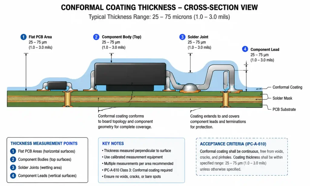
Conformal coating is a thin polymeric film applied to assembled PCBs to protect components and copper traces from moisture, dust, chemicals, and temperature extremes. The coating thickness typically ranges from 25 to 75 microns, conforming to the board topology while maintaining electrical insulation and environmental protection.
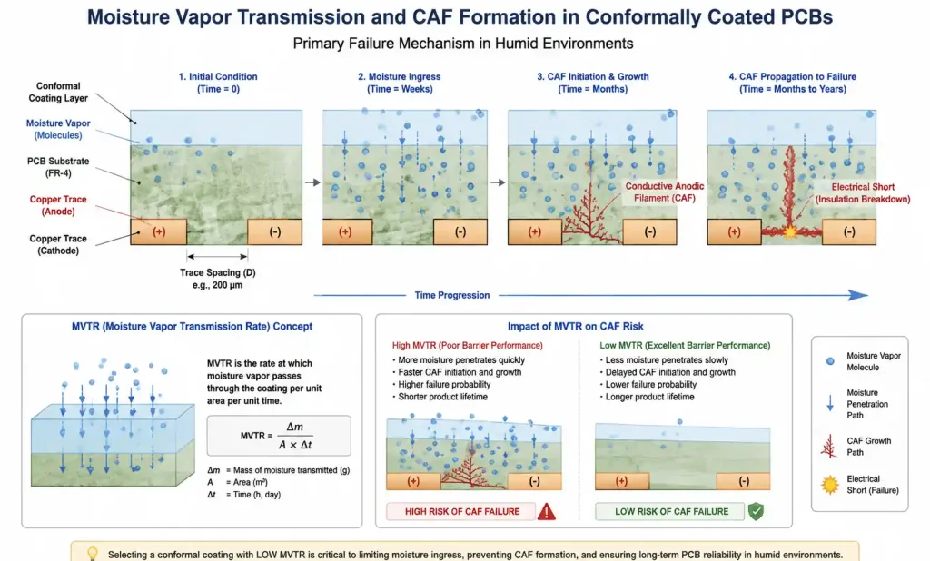
The wrong coating choice leads to measurable reliability failures. Field data from automotive and industrial applications shows that inadequate moisture protection causes conductive anodic filament (CAF) growth between closely spaced traces, while thermal expansion mismatch between coating and substrate creates cracking at solder joints. For high-voltage applications, insufficient dielectric strength results in arc tracking and insulation breakdown.
Selection criteria must balance multiple engineering trade-offs. A coating with excellent chemical resistance may have poor flexibility, leading to stress cracking during thermal cycling. High-temperature performance often comes with difficult rework procedures, creating downstream manufacturing challenges. Understanding these trade-offs requires matching coating material properties to actual operating conditions and reliability requirements.
IPC-HDBK-830 provides detailed guidance on conformal coating selection, application, and inspection. For mission-critical applications in aerospace and medical devices, IPC-A-610 Class 3 workmanship standards apply additional requirements for coating coverage, thickness uniformity, and visual defects. Military electronics must meet MIL-I-46058 specifications, which define performance under extreme environmental exposure including salt fog, fungus resistance, and thermal shock.
2. Five Main Types of Conformal Coatings Compared
PCB conformal coatings fall into five main material families, each with distinct chemical composition and performance characteristics. The selection starts with understanding these fundamental differences.
| Coating Type | Chemical Base | Dielectric Strength (V/mil) | Operating Temp Range (°C) | Flexibility | Moisture Resistance | Chemical Resistance | Rework Difficulty |
|---|---|---|---|---|---|---|---|
| Acrylic (AR) | Acrylic resin | 1000-1500 | -40 to +125 | Excellent | Good | Fair | Easy (solvent removal) |
| Silicone (SR) | Siloxane polymer | 400-800 | -60 to +200 | Excellent | Excellent | Good | Difficult (mechanical removal) |
| Urethane (UR) | Polyurethane | 1500-2000 | -40 to +130 | Good | Excellent | Excellent | Moderate (solvent + heat) |
| Epoxy (ER) | Epoxy resin | 1500-2500 | -40 to +150 | Poor | Excellent | Excellent | Very difficult (grinding) |
| Parylene (XY) | Para-xylylene | 5000-7000 | -200 to +150 | Good | Excellent | Excellent | Impossible (destructive) |
Acrylic coatings dominate consumer electronics and general industrial applications due to easy application and simple rework. The coating cures rapidly at room temperature and can be removed with isopropyl alcohol or specialized acrylic strippers. However, acrylic provides only moderate chemical resistance and softens above 100°C, limiting use in automotive under-hood or power conversion applications.
Silicone coatings excel in extreme temperature environments and maintain flexibility across the widest operating range. The low surface tension allows excellent penetration around densely packed components, but this same property makes silicone difficult to contain during selective coating. Rework requires mechanical abrasion since silicone resists most solvents. For high-reliability applications requiring field repair capability, silicone presents significant maintenance challenges.
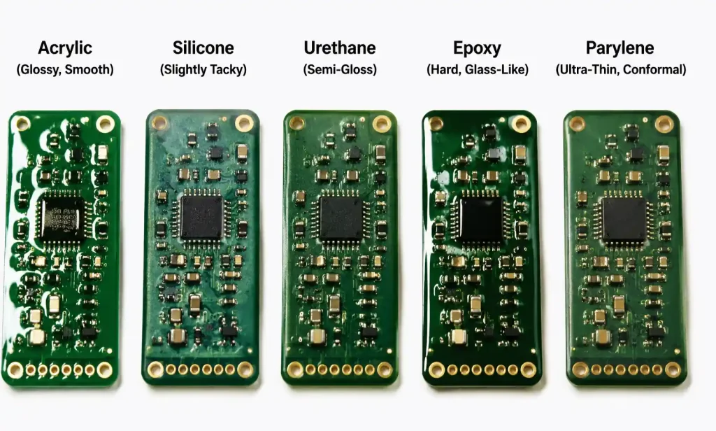
Urethane coatings offer the best balance of properties for harsh environment applications. The superior moisture barrier and chemical resistance protect boards exposed to hydraulic fluids, fuels, and cleaning agents in automotive and aerospace systems. Urethane adheres well to most solder mask surfaces and provides good abrasion resistance. The primary limitation is sensitivity to humidity during cure, which can cause cloudiness or reduced adhesion if not controlled during application.
Epoxy coatings deliver maximum environmental protection and mechanical strength but sacrifice rework capability. Once cured, epoxy forms a hard, inflexible layer that cannot be easily removed without damaging components. This makes epoxy suitable only for applications where field repair is not anticipated, such as permanently sealed industrial controllers or underground infrastructure electronics.
Parylene represents a specialized vapor-deposition coating with unique properties. The coating is applied in a vacuum chamber where para-xylylene dimer sublimates, deposits molecularly on all exposed surfaces, and polymerizes into a pinhole-free film. Parylene provides the highest dielectric strength and moisture barrier of any conformal coating, making it the preferred choice for implantable medical devices and critical aerospace electronics. The limitation is cost: parylene application requires specialized equipment and cannot be selectively applied, coating the entire assembly including connectors unless they are masked.
3. Critical Selection Criteria for Your Application
Effective coating selection requires systematic evaluation of operating conditions, reliability requirements, and manufacturing constraints. The following decision framework guides material choice based on dominant failure modes and performance drivers.
Temperature Extremes and Thermal Cycling
The coating must maintain protective properties and remain bonded to the substrate across the expected temperature range. Glass transition temperature (Tg) determines where the coating transitions from hard to rubbery state. Operating continuously above Tg causes softening, reduced dielectric strength, and potential outgassing.
For automotive ECUs experiencing -40°C to +125°C with rapid thermal cycling, coefficient of thermal expansion (CTE) mismatch between coating and substrate creates interfacial stress. Flexible coatings like acrylic and silicone accommodate this stress through elastic deformation, while rigid epoxy coatings can crack or delaminate at solder joints and component leads.
Humidity and Condensing Moisture
Moisture ingress is the primary failure mode for electronics in industrial and outdoor applications. Coating moisture vapor transmission rate (MVTR) determines how quickly water permeates through the film to reach copper traces. Lower MVTR values provide better long-term protection.
| Coating Type | MVTR (g/m²/24hr at 38°C, 90% RH) | Typical Protection Duration in Condensing Environment |
|---|---|---|
| Acrylic | 15-30 | 6-12 months |
| Urethane | 5-10 | 2-3 years |
| Silicone | 50-100 | 3-6 months (high rate but excellent recovery) |
| Epoxy | 2-5 | 5+ years |
| Parylene C | 0.5-1 | 10+ years |
The table shows MVTR values for standard coating thicknesses of 50-75 microns. Silicone has high MVTR but unique properties: absorbed moisture does not cause hydrolysis or plasticization, and the coating returns to full protective performance when dried. This makes silicone effective for applications with intermittent condensation exposure despite the high permeation rate.
For PCBs with high-density interconnect and fine-pitch components below 0.4mm, moisture trapped between coating and substrate during cure creates hidden corrosion sites. Pre-coating bake cycles at 80-100°C for 2-4 hours remove absorbed moisture from PCB laminates and reduce this risk.
Chemical Exposure
Industrial control boards face exposure to hydraulic oils, cutting fluids, cleaning solvents, and fuel vapors. Coating chemical resistance depends on polymer chemistry and crosslink density. Urethane and epoxy coatings resist most non-polar solvents and petroleum products. Acrylic coatings swell or soften when exposed to ketones, esters, and aromatic hydrocarbons.
Test data from MIL-I-46058C specifies chemical resistance requirements: coatings must show no cracking, blistering, or loss of adhesion after 24-hour immersion in specified test fluids followed by visual inspection. For custom applications with specific chemical exposure, accelerated testing using actual field chemicals provides validation before production commitment.
Dielectric Strength and High-Voltage Spacing
Power electronics and high-voltage control circuits require coatings with high dielectric strength to prevent arc tracking between conductors. Dielectric strength increases with coating thickness, but excessive thickness creates stress at component edges and interferes with heat dissipation.
For circuits operating above 250VAC or 400VDC, minimum coating thickness should be 2 mils (50 microns) with urethane, epoxy, or parylene materials. Acrylic and silicone coatings may require 3-4 mils to achieve equivalent insulation performance. IPC-2221B provides spacing requirements between conductors at different voltage levels; conformal coating allows reduction of these spacings by providing additional insulation.
However, conformal coating cannot compensate for inadequate PCB design clearances in high-voltage applications. Coating thickness varies with board topology, thinning over sharp edges and thickening in corners. Design rules should maintain minimum uncoated spacing for the operating voltage, treating coating as supplemental protection rather than primary insulation.
4. Application Method Impact on Coating Performance
The application method determines coating thickness uniformity, coverage completeness, and manufacturing cost. Method selection must consider production volume, board complexity, and selective coating requirements.
| Application Method | Typical Thickness Range | Thickness Uniformity | Equipment Cost | Best For | Limitations |
|---|---|---|---|---|---|
| Brush application | 75-150 µm | Poor | $0 | Rework, prototypes | Inconsistent coverage |
| Dip coating | 25-75 µm | Good (if drainage optimized) | Low | Simple boards, high volume | Cannot selectively coat |
| Spray coating | 25-100 µm | Fair to good | Medium | General production | Overspray waste |
| Selective coating | 50-150 µm | Excellent | High | Complex assemblies | Slower cycle time |
| Parylene vapor deposition | 5-50 µm | Excellent | Very high | Medical, aerospace | Requires vacuum chamber |
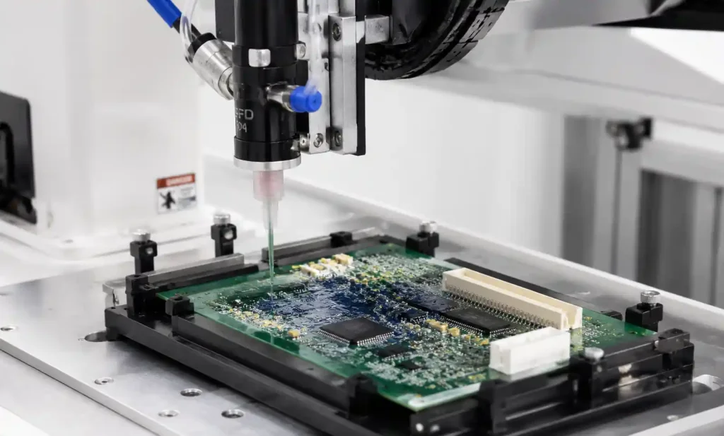
Spray coating dominates PCB assembly operations due to flexibility and moderate cost. Automated spray systems use programmable robot paths to apply coating while masking fixtures protect connectors, switches, and test points. The challenge is achieving uniform thickness on complex board topologies with tall components that shadow adjacent areas.
Multi-axis selective coating machines with needle or small-diameter spray nozzles apply coating only where needed, eliminating masking for many designs. The system follows programmed paths from CAD data, dispensing coating in controlled patterns. This approach works well for boards with many connectors and components requiring coating exclusion, but cycle time increases proportionally with coating area.
Masking and Keep-Out Considerations
Components and board features requiring coating exclusion must be masked during application or selectively avoided. Common keep-out areas include edge connectors, programming headers, test points, pressure sensors, LEDs, displays, switches, and heat sinks requiring thermal contact.
Masking methods include liquid peelable masks, tape, boots, and mechanical fixtures. Peelable masks offer precision for small features but add process steps for application and removal. For high-volume production, custom fixtures with silicone boots that seal over excluded components provide repeatable masking with minimal labor.
Design for coating (DFC) guidelines recommend grouping components requiring masking in common board areas to simplify fixture design. Connectors should mount on board edges rather than central locations to avoid coating shadows. Components requiring coating should have sufficient spacing (minimum 0.5mm) to allow coating penetration to the PCB surface.
5. Industry-Specific Requirements and Standards
Different industries impose varying conformal coating requirements based on reliability expectations, environmental severity, and regulatory oversight. Understanding these requirements early in the design phase prevents costly requalification later.
Automotive Electronics
Automotive applications follow AEC-Q200 qualification requirements for passive components and broader OEM specifications for assembled boards. Conformal coating must survive the following environmental tests without cracking, delamination, or loss of electrical properties:
- Temperature cycling: -40°C to +125°C, 1000+ cycles
- High-temperature storage: +150°C for 1000 hours
- Salt spray exposure: 5% NaCl fog, 96 hours (per ISO 9227)
- Thermal shock: -40°C to +100°C transition in less than 1 minute
- Vibration: 10-2000 Hz sweep per IEC 60068-2-64
Urethane coatings dominate automotive applications due to chemical resistance to fuels, oils, and underbody spray. For under-hood ECUs experiencing direct heat exposure from the engine, silicone coatings maintain flexibility and adhesion at elevated temperatures where urethane begins to degrade.
Medical Device Electronics
Medical devices requiring sterilization present unique coating challenges. Repeated steam sterilization cycles at 134°C with saturated steam cause hydrolysis in some coating materials. Gamma and electron-beam sterilization expose coatings to ionizing radiation that can break polymer chains and degrade properties.
Parylene C and N coatings maintain stability through repeated sterilization cycles and provide biocompatible surfaces meeting USP Class VI and ISO 10993 requirements. For implantable devices, parylene’s pinhole-free coverage prevents moisture ingress that would cause corrosion of hermetically sensitive components.
Aerospace and Defense
Military and aerospace applications follow MIL-I-46058C specifications defining coating material properties and performance requirements. The standard classifies coatings by type (AR, ER, SR, UR, XY) and requires qualification testing including:
- Dielectric withstanding voltage: 1500V minimum for 1 minute
- Insulation resistance: >10^9 ohms after humidity conditioning
- Thermal shock: -65°C to +125°C, 10 cycles
- Fungus resistance: 28-day exposure to mixed fungal cultures
- Salt fog: 5% NaCl, 96 hours per ASTM B117
For space applications, outgassing properties become critical. NASA SP-R-0022A specifications limit total mass loss (TML) to 1% and collected volatile condensable material (CVCM) to 0.1% when tested at 125°C in vacuum. Silicone coatings generally meet these requirements, while some urethane and acrylic formulations require vacuum bake-out to reduce outgassing.
6. Common Coating Failures and How to Prevent Them
Field failures traced to conformal coating issues fall into several categories. Understanding root causes enables better material selection and process control.
Coating Delamination and Cracking
Delamination occurs when coating separates from the substrate, creating voids that trap moisture and contamination. Primary causes include:
- Poor surface preparation: oils, flux residue, or oxidation preventing adhesion
- Moisture contamination: absorbed water in PCB laminate causing blistering during cure
- CTE mismatch: thermal cycling stress exceeding coating elongation capability
- Insufficient cure: coating not fully crosslinked retains internal stress
Prevention requires consistent surface preparation with cleaning or plasma treatment to improve wetting. Aqueous or solvent cleaning removes flux residue that blocks coating adhesion. For no-clean flux assemblies, evaluate coating compatibility with specific flux chemistry through adhesion testing.
Pre-coating moisture bake at 80°C for 2-4 hours removes water absorbed in PCB laminates during storage. High-Tg materials like FR4 TG170 absorb less moisture than standard FR4, reducing bake time requirements.
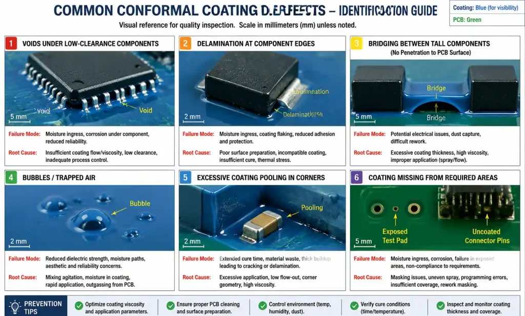
Coating Voids and Insufficient Coverage
Voids leave copper traces unprotected, allowing corrosion initiation. Common void locations include:
- Under low-clearance components: coating bridges across rather than flowing to PCB surface
- Between closely-spaced tall components: shadowing prevents coating deposition
- Fine-pitch connector pins: surface tension prevents coating penetration
Selective coating with needle dispensing provides better penetration under low-profile components compared to spray methods. For dip coating, board orientation during withdrawal affects drainage and coating distribution. Withdrawing boards at angles between 5-15° from vertical allows excess coating to drain while maintaining uniform coverage.
Coating Incompatibility with Components
Some components degrade when exposed to coating materials or solvents. Tactile switches may become sticky or unresponsive when coating penetrates the mechanism. Relays and connectors with precious metal contacts can experience increased contact resistance if coating forms insulating films.
Piezoelectric buzzers and speakers require acoustic openings kept coating-free to maintain sound output. Pressure sensors with vent ports must remain uncoated to sense ambient pressure. LEDs may experience color shift or reduced brightness if coating yellows or clouds during thermal aging.
Component datasheets should specify coating compatibility, but testing is recommended for mission-critical designs. Accelerated aging at maximum operating temperature with coated samples validates compatibility before production.
7. FAQ
What thickness of conformal coating is required for adequate protection?
Most applications require 25-75 microns (1-3 mils) of cured coating thickness. Measure thickness using a non-destructive coating thickness gauge over flat PCB areas away from components. For high-voltage applications above 250VAC, minimum thickness should be 50 microns. Thickness uniformity matters more than absolute thickness—coatings that thin over component edges or pool in corners provide inconsistent protection.
Can conformal coating be applied over no-clean flux residue?
Yes, but compatibility depends on flux chemistry and coating type. Low-solids no-clean fluxes generally work with acrylic, urethane, and silicone coatings. High-reliability applications should clean flux residue before coating to prevent long-term electrochemical migration. Test coating adhesion by attempting to peel coating from the board after cure—poor adhesion indicates incompatibility requiring cleaning.
How do you rework or repair a conformal coated board?
Rework difficulty varies by coating type. Acrylic coatings remove easily with isopropyl alcohol or commercial acrylic strippers. Silicone requires mechanical abrasion using abrasive pads or micro-blasting. Urethane coatings soften with heat and specific solvent blends. Epoxy and parylene cannot be selectively removed without damaging components. Design boards requiring frequent rework with acrylic or urethane coatings only.
Does conformal coating provide protection against electrostatic discharge?
No. Conformal coatings are insulators that do not dissipate static charge. ESD-sensitive components require proper PCB grounding, transient voltage suppression, and handling procedures. Some specialized coatings incorporate conductive fillers to provide static dissipation, but these are niche products not widely used in commercial electronics.
What is the difference between UL-recognized and IPC-qualified coatings?
UL 746E recognition validates coating material properties including flammability, dielectric strength, and temperature rating. IPC-CC-830 qualification tests coating performance under environmental stress including humidity, thermal cycling, and chemical exposure. High-reliability applications require both certifications. Check coating datasheets for UL file numbers and IPC-CC-830 compliance statements.
Can you apply multiple coats to increase protection?
Yes, but with limitations. Multiple thin coats provide better penetration around components than single thick coats. Total thickness should not exceed 150 microns to avoid coating stress and heat dissipation issues. Each coat must fully cure before applying the next to prevent solvent entrapment. For maximum protection, choose a coating with inherently better barrier properties rather than applying excessive thickness.
How long does conformal coating last in outdoor environments?
Coating lifetime depends on environmental severity, material type, and thickness. Urethane and epoxy coatings typically provide 5-10 years of protection in industrial outdoor applications with temperature cycling and humidity. UV exposure degrades some coatings—specify UV-resistant formulations for direct sunlight exposure. Annual inspection and recoating of damaged areas extends service life in harsh environments.
What are acceptable visual defects in conformal coating per IPC standards?
IPC-A-610 Class 2 allows bubbles up to 1.5mm diameter if not over bare conductors, slight orange peel texture, and color variation. Class 3 (high-reliability) is more restrictive: bubbles must be less than 0.5mm, no coating runs or sags, uniform thickness, and full coverage over all circuitry. Coating should not wick up component leads more than one lead diameter above the board surface.
8. Conclusion
Choosing a conformal coating is all about matching material properties to your real environment, reliability goals, and what your assembly line can handle. For most consumer and commercial gear with moderate exposure, acrylics are cheap and rework‑friendly. Automotive and industrial? Go with urethane—it handles chemicals and thermal cycling better. Medical and aerospace often justify the cost and hassle of parylene for maximum reliability.
Start by defining actual operating conditions, not worst‑case specs. A board that lives in a climate‑controlled room doesn’t need the same protection as one exposed to outdoor extremes. And do accelerated testing with candidate coatings before you commit—it’s cheap insurance.
Talk to your PCB assembler early in design to understand their coating capabilities and design‑for‑coating rules. Proper component spacing, connector placement, and test point locations make application easier and cheaper. For prototypes, get sample boards coated to check coverage and appearance before volume.Need help specifying coating for your next project? Our CAM team can review your design files and recommend the right material and process based on your environment and reliability needs.