Conformal Coating vs Encapsulation in PCB Assembly: A Comprehensive Comparison Guide
When designing PCBs for harsh environments, choosing the right protection method is critical for long-term reliability. Both conformal coating and encapsulation provide environmental protection, but they differ significantly in application, performance characteristics, and cost implications. This guide helps PCB design engineers, manufacturing engineers, and procurement managers understand when to use each method based on technical requirements and application constraints.
Table of Contents
- Introduction: Why PCB Protection Methods Matter
- Conformal Coating vs Encapsulation: Key Differences at a Glance
- Conformal Coating: Materials, Application Methods, and Performance
- Encapsulation: Process, Material Selection, and Protection Level
- Performance Comparison: Protection Level, Thermal Management, and Repairability
- Application Scenario Analysis: When to Choose Each Method
- Cost, Lead Time, and Manufacturing Considerations
- FAQ
- Conclusion
1. Introduction: Why PCB Protection Methods Matter
PCB assemblies operating in automotive, industrial, medical, and outdoor applications face constant exposure to moisture, dust, chemicals, thermal cycling, and mechanical vibration. Without proper protection, these environmental stressors cause corrosion, dendrite growth, electrical leakage, and ultimately field failures that result in costly warranty claims and product recalls.
Both conformal coating and encapsulation are established IPC-compliant protection methods, but they solve different engineering problems. Conformal coating applies a thin polymer layer (typically 25-75 microns) that conforms to component topography while maintaining component visibility and allowing rework. Encapsulation embeds the entire assembly or specific areas in a thick potting compound (1-5mm or more), providing superior mechanical protection and complete moisture barrier but sacrificing repairability.
The decision between these two methods depends on six critical factors: required protection level per IPC-CC-830 or MIL-I-46058, operating environment classification, thermal dissipation requirements, field serviceability needs, production volume, and total cost of ownership. Many engineers default to conformal coating without evaluating whether their application actually requires the enhanced protection that only encapsulation can provide, or conversely, they over-engineer with encapsulation when a properly applied coating would suffice.
This guide provides a parameter-by-parameter comparison based on real manufacturing data, material datasheets, and field performance studies to help you select the optimal protection method for your specific PCB assembly requirements.
2. Conformal Coating vs Encapsulation: Key Differences at a Glance
Before diving into detailed technical analysis, understanding the fundamental differences helps frame the decision criteria.
| Parameter | Conformal Coating | Encapsulation |
|---|---|---|
| Thickness | 25-75 microns (1-3 mils) | 1-5mm or more |
| Coverage | Surface coverage only | Complete volumetric filling |
| Weight added | 0.5-2g per 100cm² | 10-50g per 100cm² |
| Thermal resistance | Low (0.01-0.05 °C/W) | Moderate to high (0.1-0.5 °C/W) depending on compound |
| Reworkability | Possible with solvent or mechanical removal | Difficult to impossible |
| Visual inspection | Components remain visible | Components obscured |
| Moisture protection | Good (humidity barrier) | Excellent (complete seal) |
| Mechanical protection | Low (vibration damping minimal) | High (shock and vibration resistance) |
| Chemical resistance | Material-dependent (varies by coating type) | Excellent (most resins) |
| Process complexity | Moderate (masking required) | High (mold design, cure monitoring) |
| Typical cost per board | $0.50-$3.00 | $5.00-$25.00 |
| IPC standard | IPC-CC-830C | IPC-HDBK-830 (potting guidance) |
This table shows that conformal coating optimizes for inspectability and rework, while encapsulation optimizes for maximum environmental and mechanical protection. The 10-100x thickness difference translates directly to weight, thermal considerations, and cost structure.
For automotive under-hood applications requiring AEC-Q200 compliance, encapsulation often becomes necessary when operating temperatures exceed 125°C with sustained exposure to oil, coolant, and road salt. For industrial control boards in IP54-rated enclosures, conformal coating typically provides sufficient protection at a fraction of the cost.
3. Conformal Coating: Materials, Application Methods, and Performance
Conformal coating technology has evolved significantly over the past decade, with new formulations addressing limitations in earlier acrylic and silicone materials. Modern coatings balance dielectric strength, moisture resistance, thermal stability, and ease of application.
Material Types and Selection Criteria
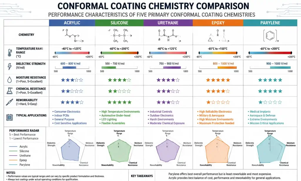
Five primary conformal coating chemistries dominate PCB manufacturing, each with distinct performance profiles:
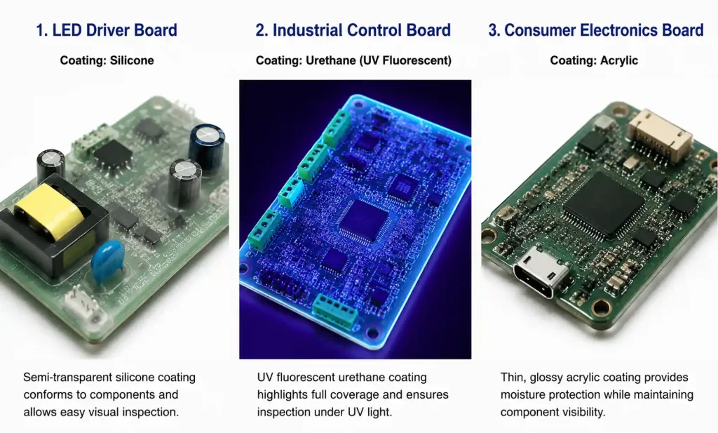
Acrylic (AR): Fast-drying, easy rework with solvents, moderate moisture protection, temperature range -40°C to +125°C. Commonly used for consumer electronics and commercial applications. Dielectric strength typically 500-1000 V/mil. Lowest cost option.
Silicone (SR): Excellent thermal stability (-65°C to +200°C), superior flexibility, good moisture resistance, but weak abrasion resistance. Difficult to remove for rework. Ideal for high-temperature applications where flexibility is critical, such as LED lighting boards and power supplies.
Urethane (UR): Outstanding chemical and abrasion resistance, excellent moisture barrier, hard surface finish. Limited temperature range (-40°C to +130°C). Difficult rework requires specialized solvents. Preferred for industrial and military applications requiring MIL-I-46058 Type UR compliance.
Epoxy (ER): Hardest coating with excellent chemical resistance, but brittle and cannot accommodate thermal expansion mismatches well. Limited use as conformal coating; more commonly used as localized potting. Temperature range -40°C to +150°C.
Parylene (XY): Vapor-deposited coating providing completely uniform coverage including under components. Exceptional moisture barrier and dielectric properties. Expensive process requiring vacuum deposition equipment. Thickness precisely controlled at 5-50 microns. Used in medical implants and aerospace applications.
Application Methods and Process Control
The coating application method significantly impacts coverage uniformity, process throughput, and material waste:
Selective spray coating uses robotic systems with programmable spray patterns to apply coating only to specified areas, reducing masking requirements. Typical film thickness control is ±15 microns. Throughput ranges from 20-60 boards per hour depending on board complexity.
Dip coating provides excellent coverage including hard-to-reach areas under components, but requires extensive masking of connectors and test points. Withdrawal speed (typically 1-10 cm/min) controls final thickness. Higher material waste due to drag-out losses.
Brush coating is limited to manual prototyping or small production runs. Thickness uniformity is poor (±30 microns), and risk of bridging between closely spaced components is high.
Vapor deposition (Parylene only) provides true conformal coverage including internal voids and crevices. Batch process with 4-8 hour cycle time including pump-down, deposition, and purge.
Process control requirements per IPC-CC-830C include monitoring coating thickness (typically via wet film thickness gauge during application or dry film measurement with magnetic or eddy current gauges), verifying cure completion (tack-free time and full cure time per material datasheet), and UV tracer verification if using UV-fluorescent coatings for inspection.
4. Encapsulation: Process, Material Selection, and Protection Level
Encapsulation transforms the PCB assembly into a sealed unit where the electronic components are completely embedded in a protective resin matrix. This approach provides maximum environmental isolation but requires careful material selection to manage thermal expansion, exothermic cure reactions, and stress on sensitive components.
Potting Compound Types and Properties
Polyurethane potting compounds: Two-part systems with excellent moisture resistance and good flexibility. Shore hardness ranges from 30A (soft, gel-like) to 80D (rigid). Typical glass transition temperature (Tg) is 60-90°C. Thermal conductivity is relatively low at 0.2-0.3 W/m·K unless filled with ceramic or metal particles. Best for applications requiring vibration damping and moderate thermal cycling.
Epoxy potting resins: Offer superior chemical resistance and higher operating temperatures (continuous service to 150-180°C depending on formulation). Available in rigid (tensile modulus 2-4 GPa) or flexible (tensile modulus 0.1-0.5 GPa) versions. Thermal conductivity can reach 1-3 W/m·K with aluminum oxide or boron nitride fillers. Epoxy systems typically have longer cure times (4-24 hours at room temperature, or accelerated cure at 80-120°C).
Silicone potting gels: Maintain flexibility across extreme temperature ranges (-60°C to +200°C) and accommodate large CTE mismatches between components and substrates. Very low modulus (Shore 00-30) minimizes stress on delicate components like MEMS sensors or large BGAs. Thermal conductivity ranges from 0.15 W/m·K (unfilled) to 2.5 W/m·K (thermally conductive grades). Higher material cost limits use to specialized applications.
Key Material Properties for Selection
| Property | Polyurethane | Epoxy (Rigid) | Epoxy (Flexible) | Silicone Gel |
|---|---|---|---|---|
| Shore hardness | 30A-80D | 75D-85D | 40A-60A | 00-30 |
| Tensile modulus | 10-1000 MPa | 2000-4000 MPa | 100-500 MPa | <10 MPa |
| Thermal conductivity | 0.2-0.8 W/m·K | 0.3-3.0 W/m·K | 0.2-1.5 W/m·K | 0.15-2.5 W/m·K |
| CTE | 80-150 ppm/°C | 50-80 ppm/°C | 100-200 ppm/°C | 300-400 ppm/°C |
| Max continuous temp | 120-130°C | 150-180°C | 130-150°C | 200-250°C |
| Cure shrinkage | 2-5% | 1-3% | 2-4% | <1% |
| Moisture absorption | 0.5-1.5% | 0.1-0.5% | 0.3-0.8% | <0.1% |
| Dielectric strength | 400-500 V/mil | 450-550 V/mil | 400-500 V/mil | 500-700 V/mil |
Material selection must balance mechanical stress on components (lower modulus reduces stress), thermal management requirements (higher thermal conductivity improves heat dissipation), and environmental protection needs (lower moisture absorption improves long-term reliability).
Encapsulation Process and DFM Considerations
The encapsulation process introduces several manufacturability considerations that must be addressed during PCB design:
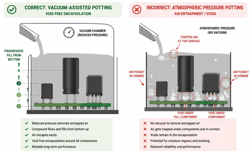
Mold design: Pot or dam encapsulation requires a containment structure, either a permanent housing integrated into the product enclosure or a temporary dam applied with room-temperature vulcanizing (RTV) silicone. Mold design must include vent paths to prevent void formation during potting.
Fill procedure: Most potting is performed under vacuum (typically 28-29 inches Hg) to eliminate entrapped air bubbles that would compromise dielectric strength and create moisture ingress paths. For large assemblies, progressive filling from the lowest point prevents void formation around tall components.
Exothermic cure management: Two-part epoxy and polyurethane systems generate heat during cure. For thick sections (>10mm), peak exotherm temperature can reach 150-180°C, potentially damaging temperature-sensitive components. Gel time selection and controlled cure schedules mitigate this risk.
Component stress: Cure shrinkage creates tensile stress at the resin-component interface. Components with large exposed metal surfaces (connectors, heat sinks) experience higher stress. Flexible formulations or stress-relief coatings applied before potting reduce failure risk.
5. Performance Comparison: Protection Level, Thermal Management, and Repairability
Understanding how conformal coating and encapsulation perform across critical parameters helps match the protection method to application requirements.
Environmental Protection Performance
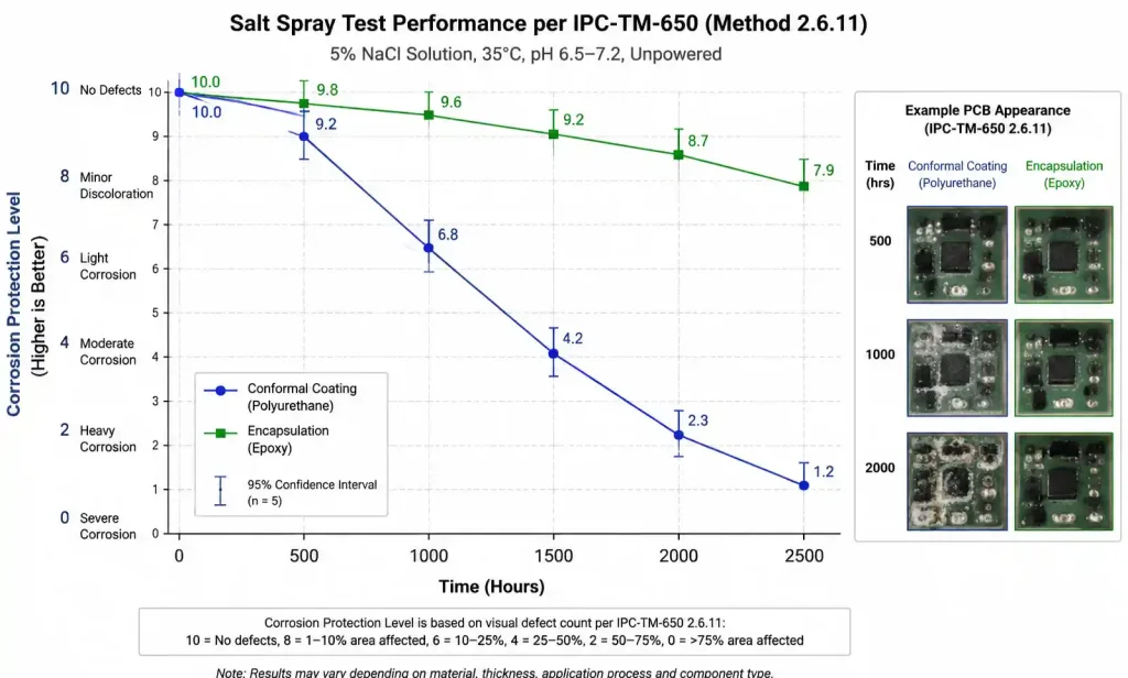
Moisture and humidity protection: Standard salt spray testing per IPC-TM-650 shows that properly applied conformal coating (50-75 micron thickness) provides protection for 500-1000 hours before corrosion initiation on exposed copper or component leads. Encapsulated assemblies withstand 2000+ hours due to the complete moisture barrier, assuming no voids or interfacial delamination. For applications requiring IP67 or IP68 ratings with sustained immersion, encapsulation is typically necessary.
Chemical exposure: Conformal coating performance is chemistry-dependent. Urethane and Parylene coatings resist automotive fluids (gasoline, diesel, brake fluid, coolant) effectively, while acrylic coatings degrade rapidly. Encapsulants, particularly epoxy systems, provide superior resistance to industrial solvents, acids, and bases.
Fungus resistance: Per MIL-STD-810 Method 508, both conformal coating and encapsulation can be formulated for fungus resistance, but the complete physical barrier of encapsulation provides inherent protection even if the resin itself supports fungal growth.
Altitude and pressure: At high altitude (low pressure), conformal coating’s thin profile maintains dielectric strength better than thick encapsulation layers, which can experience internal stress from outgassing during rapid pressure changes. For avionics applications above 50,000 feet, properly cured conformal coatings are often preferred.
Thermal Management Trade-offs
Thermal resistance of the protection layer directly impacts component junction temperatures and overall system reliability:
Conformal coating adds minimal thermal resistance (0.01-0.05 °C/W for typical coating thickness and PCB area) and does not significantly alter the thermal design. For power semiconductors with exposed thermal pads, coating allows direct thermal connection to heatsinks or metal-core PCBs.
Encapsulation adds measurable thermal resistance that must be accounted for in thermal simulations. A 3mm thick polyurethane layer with 0.3 W/m·K thermal conductivity over a 1cm² component contributes approximately 0.1 °C/W thermal resistance. For a 5W power component, this translates to a 0.5°C junction temperature increase. Thermally conductive formulations (1-3 W/m·K) reduce this impact but increase material cost by 3-5x.
Design mitigation strategies for encapsulated power modules include using aluminum or copper core PCBs for improved lateral heat spreading, integrating metal heat spreaders that conduct heat out of the encapsulant to external surfaces, and selecting low-exotherm formulations that cure at lower temperatures.
Rework and Repairability
Conformal coating removal for rework is achievable using several methods depending on coating chemistry:
- Acrylic: Solvent removal with isopropyl alcohol or specialized strippers
- Silicone: Mechanical peeling or cutting (time-consuming, risk of component damage)
- Urethane: Chemical strippers or thermal degradation with hot air (requires care to avoid substrate damage)
- Parylene: Mechanical abrasion or plasma etching (specialized equipment required)
After component replacement, local re-coating is performed, though achieving perfect blend with the original coating is difficult. For IPC Class 3 applications, full strip and re-coat may be required.
Encapsulation removal is destructive. Mechanical milling, grinding, or routing can remove bulk material, but component extraction typically damages the component, adjacent parts, or the PCB itself. For critical applications requiring field service, design approaches include potting only non-serviceable sections while leaving serviceable components accessible, or designing modular assemblies where entire encapsulated modules are replaced as units.
6. Application Scenario Analysis: When to Choose Each Method
Selecting the optimal protection method requires analyzing your specific application environment, reliability requirements, and lifecycle cost constraints.
Choose Conformal Coating When:
Consumer electronics and commercial equipment operating in climate-controlled environments (office, home, retail) where primary threats are dust accumulation and occasional condensation. Acrylic or urethane coatings meeting IPC-CC-830 Class 2 requirements provide adequate protection at lowest cost.
Industrial control boards in IP-rated enclosures where the enclosure provides primary environmental protection and the coating provides backup protection against dust ingress and condensation during thermal cycling. Urethane coating (75 micron thickness) is typical for these applications.
LED lighting assemblies requiring high-temperature operation (junction temperatures 100-140°C) where silicone conformal coating provides both environmental protection and flexibility to accommodate thermal expansion without adding significant thermal resistance.
Test and measurement equipment and other applications requiring frequent calibration, repair, or component updates. Conformal coating allows visual inspection and rework without destroying the assembly.
High-density PCBs with BGAs and fine-pitch components where thick encapsulation would trap voids under low-standoff components. Thin conformal coating or Parylene deposition provides environmental protection without voiding risk.
Choose Encapsulation When:
Automotive under-hood applications (engine control units, transmission controllers, fuel injection systems) requiring AEC-Q100 or AEC-Q200 qualification with sustained exposure to temperatures up to 150°C, thermal cycling from -40°C to +150°C, and chemical exposure to oils, fuels, and coolants. Flexible epoxy or polyurethane encapsulation is standard.
Outdoor infrastructure equipment (telecommunications, solar inverters, traffic control) exposed to UV radiation, rain, freeze-thaw cycles, and industrial pollutants. IP67 or IP68 rated encapsulation provides long-term protection in unmaintained installations.
High-voltage power supplies and inverters (above 600V) where the potting compound provides essential electrical insulation and creepage distance in addition to environmental protection. Rigid epoxy formulations with high dielectric strength (>500 V/mil) are used.
Harsh industrial environments (chemical processing, mining, marine) where exposure to aggressive chemicals, high-pressure washdown, or mechanical impact exceeds conformal coating capabilities. Chemically resistant epoxy encapsulation is standard.
Security and tamper-evident applications where encapsulation serves dual purposes of environmental protection and physical security against reverse engineering or unauthorized modification.
Sensor modules and transducers requiring stable, stress-isolated mounting of sensitive elements (MEMS accelerometers, pressure sensors, precision resistors). Soft silicone gel encapsulation provides mechanical isolation while maintaining low stress.
Hybrid Approaches
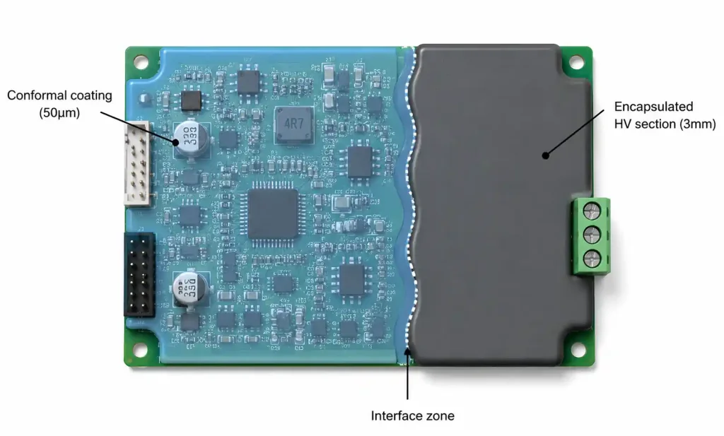
Some designs combine both methods to optimize protection and cost. For example, applying conformal coating to the entire PCB for general environmental protection, then selectively encapsulating high-voltage sections, sensitive sensor areas, or connectors requiring IP67 sealing. This approach requires careful process sequencing: conformal coat first, cure completely, then mask and encapsulate selected areas.
7. Cost, Lead Time, and Manufacturing Considerations
Total cost of ownership includes direct material and process costs plus downstream impacts on testing, quality control, and field service.
Direct Cost Comparison
| Cost Element | Conformal Coating | Encapsulation |
|---|---|---|
| Material cost | $0.20-$0.80 per board | $2.00-$15.00 per board |
| Masking materials | $0.10-$0.40 per board | $0.50-$2.00 per board (dams/molds) |
| Process labor | $0.15-$0.50 per board | $1.00-$5.00 per board |
| Equipment amortization | $0.05-$0.25 per board | $0.50-$3.00 per board |
| Curing energy cost | $0.02-$0.08 per board | $0.10-$0.50 per board |
| Inspection cost | $0.05-$0.15 per board | $0.15-$0.30 per board |
| Total per board | $0.57-$2.18 | $4.25-$25.80 |
These costs scale with board area, coating/potting thickness, and production volume. High-volume production (>10,000 units/year) with automated selective coating systems achieves the lower end of the cost range. Low-volume production (<1,000 units/year) with manual processes tends toward the higher end.
Process Cycle Time and Throughput
Conformal coating cycle time (mask → coat → cure → inspect → demask) ranges from 15 minutes to 4 hours depending on coating chemistry and cure schedule. Acrylic coatings with solvent evaporation cure achieve 20-40 boards per hour throughput. UV-cure coatings offer the fastest cycle (coating + cure in <5 minutes) but have higher material cost. Moisture-cure silicones and urethanes require 4-24 hour cure before handling.
Encapsulation cycle time (prepare → pot → degas → cure → inspect) typically requires 1-3 days. Most potting compounds require 4-8 hour room-temperature cure before handling, with full cure achieved in 24-72 hours. Elevated temperature cure schedules (80-120°C) accelerate this to 1-4 hours but add oven time and energy cost. Vacuum degassing adds 15-30 minutes per batch.
Quality Control and Testing
Conformal coating inspection verifies coverage completeness, thickness uniformity, and absence of defects (bridging, voids, contamination). Methods include:
- Visual inspection under UV light (for UV-fluorescent coatings)
- Wet/dry film thickness measurement at specified locations
- Adhesion testing per IPC-TM-650 2.4.28
- Dielectric withstand testing at specified voltage
Encapsulation inspection focuses on void detection (X-ray or ultrasonic scanning), cure verification (Shore hardness measurement), and interface integrity (pull testing for bonded connectors or bushings). Non-destructive X-ray inspection adds $5-20 per assembly depending on complexity.
Supply Chain and Lead Time Considerations
Conformal coating materials have broad supply availability with 2-4 week lead times for standard formulations. Custom color matching or UV fluorescence intensity may extend to 6-8 weeks.
Potting compounds, especially thermally conductive or specialty formulations, have longer lead times (6-12 weeks) and higher minimum order quantities (20-200 kg). Supply chain disruptions can severely impact production since potting compound qualification testing makes rapid supplier changes difficult.
8. FAQ
What is the minimum coating thickness required for effective moisture protection?
Per IPC-CC-830C, minimum dry film thickness is 25 microns (1 mil) measured at the lowest point. However, for reliable moisture protection in condensing humidity environments, 50-75 microns (2-3 mils) is recommended. Thickness below 25 microns often has pinholes or insufficient coverage over sharp component edges.
Can conformal coating and encapsulation be used together on the same PCB?
Yes, this is common in mixed-voltage designs where low-voltage circuitry receives conformal coating for cost efficiency while high-voltage sections (>300V) are encapsulated for enhanced dielectric insulation. Apply and cure the conformal coating completely before masking and encapsulating selected areas. Ensure chemical compatibility between coating and potting compound.
How does encapsulation affect high-frequency RF circuit performance?
Potting compounds with dielectric constant (Dk) of 3-5 alter stripline and microstrip impedance and increase insertion loss, particularly above 1 GHz. For RF circuits, use low-Dk silicone gels (Dk ~2.5, Df <0.001) or apply conformal coating only. Alternatively, design RF sections with impedance adjusted to account for encapsulant dielectric loading.
What’s the maximum operating temperature for conformal coated assemblies?
This depends on coating chemistry: acrylic (125°C), urethane (130°C), epoxy (150°C), silicone (200°C), Parylene (200-250°C depending on type). These are continuous operating temperatures; short excursions during reflow or rework may exceed these values. Always verify coating glass transition temperature (Tg) to ensure mechanical properties remain stable.
Is rework possible after encapsulation?
Practical rework of encapsulated assemblies is extremely difficult. Mechanical routing or milling can remove bulk material, but component extraction typically damages the component, nearby parts, or PCB traces. For products requiring field service, design modular architectures where entire encapsulated subassemblies are replaced rather than repaired.
How do I choose between rigid and flexible encapsulation formulations?
Select based on thermal cycling requirements and component stress sensitivity. Rigid epoxy (Shore D 75-85) minimizes volume and provides maximum mechanical protection but generates high stress during thermal cycling (CTE mismatch). Flexible polyurethane or soft epoxy (Shore A 40-60) accommodates thermal expansion and reduces component stress but requires larger volumes and provides less mechanical rigidity. For assemblies with large BGAs, high-power components, or wide temperature cycling (-40°C to +125°C), flexible formulations reduce failure risk.
What IPC standards govern conformal coating and encapsulation processes?
Conformal coating is covered by IPC-CC-830C (material qualification) and IPC-A-610 Section 10 (acceptance criteria for coating application). Encapsulation processes follow guidance in IPC-HDBK-830 and IPC-A-610 Section 11. For military applications, MIL-I-46058 specifies coating types and performance requirements, while MIL-STD-2041 covers application methods.
How long do conformal coatings and encapsulants maintain their protective properties?
Service life depends on material chemistry and environmental exposure. Urethane and silicone conformal coatings typically maintain protective properties for 10-15 years in industrial environments before UV degradation or chemical exposure causes performance decline. Epoxy and polyurethane encapsulants maintain mechanical and moisture barrier properties for 15-25 years. Parylene coatings are extremely stable and can maintain properties for 20+ years. Accelerated aging testing per IPC-TM-650 2.6.3 predicts service life for your specific application conditions.
9. Conclusion
Picking between conformal coating and encapsulation really boils down to three things: How much protection do you actually need? Can you live with the thermal and repairability downsides of encapsulation? And what does the total lifecycle cost look like—including field failures?For most commercial and industrial stuff in controlled or mildly harsh environments, a properly specified coating does the job at much lower cost. Just match the chemistry to your specific exposures and lay down enough thickness (50–75 µm minimum) for reliable coverage.
Encapsulation only makes sense when you’re dealing with sustained liquid immersion, aggressive chemicals, extreme thermal cycling, or heavy shock and vibration that coating can’t handle. The extra cost and design complexity are worth it if field failures would otherwise kill your reputation or safety.
Designing a board for harsh conditions and not sure which way to go? Send us your files and environmental specs for a free DFM review. We’ll recommend coating or encapsulation, material choices, and process tweaks to hit both reliability and cost.